"QuickieLab"
BASIC computing platform for ham radio experiments
![]()
"QuickieLab"
BASIC
computing platform for ham radio experiments
![]()
Build this simple BASIC Stamp board designed especially for ham radio RF, control and measurement experiments.
Serves as the instructional platform for noted ham radio author Joe Everhart, N2CX in his regular columns in QRP Quarterly magazine (Joe's Quickies and Test Topics and More), and in other feature articles in QRP Homebrewer magazine.
These QuickieLab web pages provide detailed construction plans, availability of PC board & specialized parts, and many specialized Application Notes including short BASIC programs and simple interface circuits showing step-by-step how to make test, measurement and operating gadgets for your radio shack.
|
|
TABLE OF CONTENTS Description full technical overview of the QuickieLab, theory of op and construction tips Schematic a complete schematic of the QuickieLab Manual - The manual distributed with the kit. Parts List a list of all parts, part numbers and supplier information Notes useful guidance for obtaining parts and building the QuickieLab Construction Notes -- Helpful tips & techniques for building up a QuickieLab Datasheet a concise listing of QuickieLab specifications QuickieLab Monitor Program a BASIC program that exercises many QuickieLab features Availability for the PC board & I/O Expander IC Focus on the BASIC Stamp tutorial on programming and using the QuickieLab (coming soon) Application Note #1 An Audio Visual Voltmeter Application Note #2 The VXO-Mate
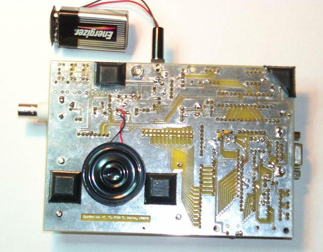
More Photos: QuickieLab with KeyPad & LCD removed Backside of QuickieLab showing speaker ~ Copyright 2003 ~ G. Heron, N2APB ~ All Rights Reserved ~ QuickieLab material may only be used for personal, non-commercial purposes. No warranty of operation is implied. QuickieLab hardware and software may not be reproduced in any manner without prior written approval of G. Heron or J. Everhart. |
Build the "QuickieLab"
INTRODUCTION
Great feedback is regularly received now from ham radio homebrewers about
how microcomputers can be used to enhance QRP experiences. Its very
gratifying and encouraging to know that so many are
interested in these types of digital projects. So when considering such useful
projects that homebrewers can easily build, the light bulb clicked on once again
during one of the lunchtime discussions that I have with my good friend and
cohort in design Joe Everhart, N2CX and we discovered that a perfect project
would be one that provides a reusable test bed for
experimentation, measurement and simple control. Further, we thought it
be great if this experimenters platform were tightly coupled with the string
of N2CX Quickies that Joe presents in
each issue of QRP Quarterly
and on the NJQRP website. This would provide
N2CX with a computing module to help illustrate his points and the readers with
a quick and easy way to reproduce the Quickie material. Hence the name of this
project was born
the QuickieLab.
THE BASIC STAMP
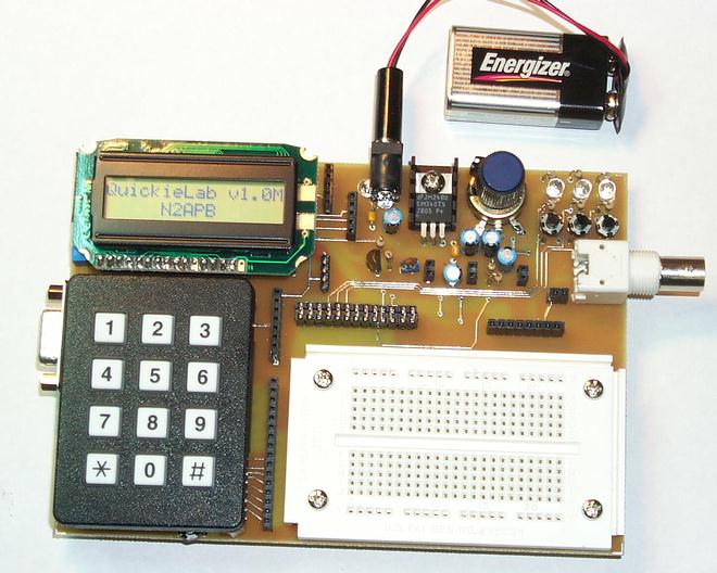
The QuickieLab is a 4.5 x 6 circuit board with keypad, LCD, switch
input and LED output capabilities built around the popular BASIC Stamp processor
from Parallax.inc. The Stamp was selected because of its easy to program BASIC
language and its simple hardware interface just connect +5V to this Stamp
chip and you can download a BASIC program from your PC to wiggle the output pins
and read the input pins as desired.
Readers wishing to follow along with N2CX and his BASIC language experiments could certainly purchase one of the many fine Stamp-based experimentation boards from Parallax.com and have a ready-to-go hardware platform with most of the capabilities described here. However, one could save quite a few pennies by building the QuickieLab and ending up with a more capable platform that is specifically geared to the growing number of Joes Quickie experiments.
Referring to the schematic, you can see that the QuickieLab is built around a BASIC Stamp microcontroller.
The Stamp merely needs to be powered with 6-to-12V dc from the QuickieLabs connector J1 and this self-contained system on a chip is ready to go. It contains an onboard 5V regulator for its computing logic and its own RS-232 levels for serial port connection to a PC. Further, the Stamp contains an internal non-volatile memory that allows retention of the software program even after power is removed. With this capability the QuickieLab can be programmed once (i.e., its software program needs only to be downloaded once from the PC), and it can forevermore operate independent from the PC umbilical cord. Take it out to the field with an appropriate battery supply or to your buddys house and itll operate the same as it last did on your bench!
I/O PINS DO ALL THE WORK
The main purpose of any microcontroller is to input various signals, do some
computations based on those signals, and then output other signals based on
those computations. Thus the Stamps sixteen I/O pins are of great interest
and utility to us in the QuickieLab. Each of the I/O pins is under software
control and can be used to read the state of pushbuttons and keypad actuations,
as well as to send data to human-readable devices like the LEDs and the LCD. The
I/O pins are wired to a jumper block J10 located directly above the plugboard
and the user may jumper any of them to components placed on the plugboard. In
this way, the components called out in the experiment may be temporarily
wired to the Stamp and controlled by the software program. For example,
you could mount a diode, resistor and a couple of capacitors on the plugboard,
jumper the output of that network to the built-in A/D converter (see following
section) and have yourself a rudimentary-but-useful RF voltmeter. In fact, this
capability is actually described in detail as the practical aspect of the
project later in this article. Joe
intends on having other useful interface circuits, software programs and
application notes available for the QuickieLab on the companion website for this
project: www.njqrp.club/quickielab.
As mentioned, a number of common I/O devices are provided on the QuickieLab board for use in the various experiments. Three pushbuttons and three LEDs are provided for simple input and output controls and indicators. Sometimes the most instructive experiment is to press a button and see a corresponding LED be illuminated under program control. A built-in potentiometer is provided and is quite useful as a control that delivers a continuously variable 0-255 binary input to the Basic program. A program can read the pot and adjust a software algorithm based on the specific setting. A simple D-to-A converter is provided to produce a DC voltage from 0-to-5V for controlling other hardware under software control. And lastly, a speaker is provided to enable the Basic program to output an audio tone that can range from 200 Hz up to 10 KHz. Cant you just imagine a an upcoming Joes Quickie application using this speaker to produce an audio dip when measuring SWR?!
Each of these built-in I/O devices is wired to a specific I/O pin of the Stamp through pinheader P1. When the corresponding pins of P1 are jumpered with configuration blocks, the respective signals are wired directly to I/O pins on the Stamp. In this way you could easily configure the QuickieLab to use its built-in components for experiments without necessarily using additional components on the plugboard. When a given built-in I/O device is not needed for the current experiment, its pins on P1 can be left open and the Stamps I/O pin on J10 may be jumpered over to something else on the plugboard.
I/O EXPANDER
Perhaps the most attractive feature of the QuickieLab, as compared to
commercially-available Stamp boards, is the custom-designed I/O expansion
processor U2. Readers of my columns in QRP Quarterly magazine will recognize the
SX-28 microcontroller used for I/O expansion here as also being used in the
PSK31 Audio Beacon and Badger smartbadge projects. This time I programmed the
SX-28 to enhance the QuickieLab by having it serve as an intermediate processor
that helps in the input and output of some additional built-in components.
The IOX project website provides
complete details on interfacing and using the I/O Expander, but heres a quick
overview of the function provided in this versatile controller.
Serial LCD Display Driver The SX-28 accepts serial commands from the BASIC Stamp to display the specified ASCII character directly, or a command character to control the cursor position and other LCD functions like clear display and scroll control. The SX-28 duplicates the simple command structure found in other serial LCD controllers, allowing the QuickieLab programmer (i.e., you) to easily display messages to the LCD display. You can clear the display, home the cursor, control scrolling and blinking, and simply display characters all by means of a serial output command from the BASIC Stamp software youve written.
Frequency Counter Another unique feature of this I/O Expander chip is its ability to measure frequency. Since this fast SX processor is sitting idle most of the time waiting to be commanded by the Stamp to display characters, I dropped in a tried-and-true software routine that samples the signal on the RTCC pin and determines its frequency. Thus when the Stamp commands a frequency measurement, the SX processor sends back certain data that represents the frequency of the input signal up to 30 MHz. This is a pretty useful feature for a QuickieLab such as ours!
A-to-D Converter Since it is important in most of our ham experiments to read an analog voltage of some sort, we felt it would great to add a simple 8-bit A/D converter as part of the built-in arsenal of components. The I/O Expander interfaces to the ubiquitous ADC0831 chip and the BASIC program in the Stamp can issue an ADC command instructing the analog conversion to be done. The 8-bit value is then returned to the Stamp controller for possible computation and display.
Keypad Yet another important I/O component contained in the I/O Expander chip is that of the software driver and hardware interface to a keypad. Useful for numeric and command entry, this 4 row x 3 column matrix keypad is constantly scanned by the SX controller. Whenever a keypress is detected, a message is sent to the main BASIC program in the STAMP controller and specific action can be taken. In this way, the programmer (i.e., N2CX with his application note software, or you with your own software experiment) may input data, set frequencies to be later output, etc.
Digital Potentiometer The final built-in I/O device controlled by the I/O Expander is a non-volatile digital potentiometer. This device is essentially an electronic pot that can be adjusted under program control to move its wiper to be at any of 100 positions. If, for example, this digital pot were jumpered into the feedback loop of an op amp on the plugboard, your BASIC Stamp program could output a command to the I/O controller to adjust the pot up or down to change gain of the amplifier stage. This is a pretty neat capability to have in our experimenters platform!
DDS DaughterCard Provisions are made on the QuickieLab to accommodate a DDS daughtercard. This small board contains the Analog Devices AD9850 Direct Digital Synthesis chip, its oscillator and the low pass output filters that all conspire to produce very precise and low-noise frequencies from the sub-hertz basement up to 30 MHz. The 1x2 daughtercard plugs into socket J6 on the QuickieLab and enables generation of a very stable and known-frequency signal source. It can be useful as a VFO, a test signal source, a local oscillator in a test receiver or even as an audio oscillator when patched into the built-in speaker on the QuickieLab.
CONSTRUCTION
Building up the QuickieLab is a piece of cake. A PC
board is
available to help homebrewers build up a QuickieLab. Alternatively, one could
easily wire up a perf board containing the few chips and connectors comprising
the project. A parts list is provided in the Notes section at the end of this
article to enable homebrewers to easily acquire the parts and construct the
QuickieLab.
The prototype QuickieLab pictured in this web site was constructed on a 4.5 x 6 piece of perf board. The keypad and LCD modules are held up off the board with standoffs and plug into connectors on the perf board to facilitate easy access to components beneath them during the construction and test phases. The SX-28 controller, voltage regulator and A/D converter chips are located under the LCD, and the BASIC Stamp chip is located under the keypad. The pushbuttons, LEDs and potentiometer are located in the upper right portion of the board. The DB9 serial connector, and DC power jack are located in the upper center area, while the plugboard can be seen in the lower right corner of the perf board. The female socket J3 containing the Stamp I/O pin signals is located directly above the plugboard to allow the user to easily place a wire jumper from any given signal in J3 to a component placed on the plugboard. Pinheader P3. Jumpers to select the built-in IO devices are located right above the STAMP I/O pin signals connector P3. The speaker is attached to the underside of the perf board. A second perf board with identical dimensions as the main board is connected beneath the main board and separated using eight standoffs. This serves to protect the underside wiring of the QuickieLab. Rubber feet are attached to the bottom perf board to allow it to stand comfortably on your work table when in use.
A 4" x 5" professional-grade printed circuit board will be available in December to assist homebrewers in easily constructing a QuickieLab.
USING THE QuickieLab
The QuickieLab is based on the BASIC Stamp. The vendor of this ingenious
device (Parallax.com) provides an excellent development suite to support
hobbyists in their programming and use of the Stamp. When you purchase the
microcontroller from Parallax, you can request a CD-ROM containing software for
your PC that allows you to create/modify your BASIC programs and download them
to the Stamp contained on the QuickieLab. Otherwise, all software contained on
the CD-ROM is also available for free download from their Stamp web pages at www.parallax.com.
Their PBASIC commands are tailored to realtime control of simple hardware
devices and there are many useful extensions to the language which are of great
value to homebrewers. The CD-ROM also contains many sample programs illustrating
basic operation of the commands and chip features. A Users Manual is provided in
PDF format on the CD to guide first time users through typical BASIC program
creation and debug sessions. A
complete PBASIC language guide is also in the Users Manual for detailed use as a
programming reference.
With all this neat development stuff provided by Parallax, you can easily have your QuickieLab up and running within an hour. All you then need to do is download the specialized QuickieLab Application Notes from the links noted at the top of this page, send the corresponding BASIC program over a serial cable to your QuickieLab platform and youll be able to keep right in step with N2CX when he comes out with the next Joes Quickie in the pages of QRP Quarterly magazine.
LIMITATIONS
The BASIC Stamp as a microcontroller and the QuickieLab as an
experimenters platform each has great potential for instruction and utility
on your workbench. However Id be remiss not to caution readers about some
limitations.
Any implementation of a Stamp microcontroller might be seen as an expensive computing solution. The BASIC Stamp starts out at $49, and the other components add up from there. A complete QuickieLab might well cost the homebrewer over $100 by the time its completed. But expensive is a relative term and some homebrewers will likely see this investment as valuable in terms of its educational and long-time reusable nature.
The QuickieLab is not a performance-oriented or extensible microcomputing platform. A very limited number of I/O pins limits how many hardware components can be connected at one time. Further, the effective speed of the Stamp is significantly slower than the HC908 Digital Breadboard project or any other native-language PIC processor, mainly because the Stamp interprets its high-level BASIC commands individually at run time, greatly slowing down its overall computing process. In contrast, the HC908 Digital Breadboard project is a far better choice for a flexible and dedicated high-performance control and measurement piece of equipment for your bench.
However even with these limitations, the QuickieLab is a great educational solution for quick-and-easy experiments that dont require lots of high speed operations. N2CX regularly tells me how utterly cool it is to be able to program an algorithm into the QuickieLab and see immediate results.
Any way you look at the QuickieLab, its easy to build, fun to use and you can bet that well be seeing lots of applications for it in future Joes Quickies. And for starters, have a go at the Audio Voltmeter application elsewhere in this issue!
PARTS LIST
The following parts may be gathered to construct the QuickieLab. All parts
are readily available from RadioShack, Mouser Electronics, Digi-Key or elsewhere
as noted. The specially-provided PC board and the I/O Expander IC may be
obtained from the NJQRP Club.
A complete kit of parts is not being provided for this project, as there are many paths that a homebrewer may take in order to keep the overall investment as low as possible.
Thanks to Tom & Nancy
Feeny for the updated/corrected Parts List below ...
(Download this Excel spreadsheet)
NOTES
A less expensive alternative to use of the Parallax BASIC Stamp is to use
the PIC-based chip set from Peter Anderson, a noted designer and author in the
pages of Nuts & Volts magazine. You can purchase his Homebrew Stamp 2 Kit
for about $22, and details are on his website www.phanderson.com.
(The QuickieLab pc board can accommodate the Homebrew Stamp chip set as
well as the BASIC Stamp.)
PRICE
The QuickieLab PC BOARD
is available for $25 from the NJQRP Club.
Shipping is free to US & Canada. (DX orders please add
$8 extra) You get a 6"x4"
double-sided printed circuit board with white silkscreen parts placement legend
on a green soldermask to assist in component placement and assembly quality. You also get the QuickieLab
Construction and Usage Manual describing many ways by which you can build,
program and utilize the QuickLab.
NOTE: You may also wish to consider getting the companion I/O Expander controller chip made specially for the QuickieLab. You can purchase this programmed chip and resonator from the NJQRP Club for $15. Further info on the IOX chip is located at http://www.njqrp.club/iox
AVAILABILITY
Sorry, sold out and the kit is retired.
![]()
![]()
![]()