QuickieLab Application Note #1
an Audio Visual Voltmeter
![]()
QuickieLab Application Note #1
an
Audio Visual Voltmeter
![]()
Configure your QuickieLab to serve as a voltmeter with Morse, Tone and LCD output
Joe Everhart, N2CX email: n2cx@voicenet.com
QuickieLab AN #1 illustrates how easy it is to make a unique test instrument with little more than the QuickieLab itself. This instrument combines the familiar digital voltmeter function with an unusual audio “readout.” It uses a number of the built-in QuickieLab functions such as analog- to-digital conversion (ADC), a liquid crystal display (LCD), on board pushbuttons and the built-in loudspeaker. It also uses the experimenter’s plugboard to provide for connection of a potentiometer and an optional op-amp buffer.
AAV Specs at a Glance
Digital
Voltmeter
3-digit
Liquid Crystal Display
Selectable
Variable Pitch Tone or Morse Numeric Output
0-2VDC
measurement range
0.01V
(0.5%) Resolution
What
is the AVV?
The AVV is a digital voltmeter. It
features the same 10 megohm input impedance we expect with commercial test
equipment to minimize circuit loading.
As described here, it reads 0 to 2 VDC with a resolution of 0.5% (0.01V)
and features a familiar 3-digit LCD readout.
(More about ranges and resolution later). However it also offers a couple
of unusual features in the form of audible outputs.
A
single pushbutton depression keeps the visual readout and adds a variable tone
output. The tone varies in pitch
from about 300 Hz to just under 3000 Hz and is proportional to the measured DC
input. This variable tone can serve
the same function as an analog bargraph display for easy observation of peaks or
dips in measured voltages – with the advantage that you don’t have to even
look at the meter. A second press
of the button changes the variable tone output to an audible three-digit Morse
code output. It reads exactly the
same value as the LCD, but as with the bar graph display you can take readings
without looking at the LCD.
Naturally
if you don’t want or need the audio outputs you don’t have to use them. In the same vein if you have a visual impairment or have to
do measurements where looking at the display is awkward or impossible, you can
“read” the meter with your ears.
The
AVV uses several of the built-in Quickielab functions.
Naturally the BS2 chip is the heart of the project, acting as a
controller to coordinate overall operation.
Using the IOX chip it reads DC input voltages, performs calculations and
outputs readings via the QuickieLab LCD screen or the loudspeaker.
QuickieLab pushbutton switch PB1 is used to select the AVV operating
mode. The experimenter’s
plugboard section is used for connecting up an input buffering operational
amplifier and ADC reference voltage adjustment potentiometer.
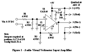
Figure 1 shows a schematic/block diagram of the AVV, showing how the added circuitry interconnects with the QuickieLab. All connections are made via jumpers from the ADC connection jack J2 too the Experimenter’s Plugboard. 5-volt operating power and ground are supplied via the connector and the buffer amplifier output and a voltage reference from potentiometer R6 sets the ADC operating level.

The
input amplifier provides a buffered input to the ADC with a 10 megohm input
impedance as is common with digital voltmeters.
It provides unity gain so that its input voltage is presented at the same
level to the ADC input pin. R6 is
adjusted for a DC voltage of exactly 2 volts on J2 pin 2.
Thus full scale on the ADC is 2 volts.
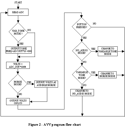
Figure 2 shows the AVV software flow chart. Most details can be seen from the figure, but the highlights are that the program begins by reading the ADC then converting the 8-bit result to a decimal number and outputting it. The output is always displayed on the LCD while the audio mode flips between a Morse output, a variable tone output or no audio with successive depressions of the QuickieLab pushbutton. Not that operation of the ADC and LCD are ‘hidden” at a low level by use of the IOX controller IC on the QuickieLab board.

A
complete program listing for the AVV can be
viewed. (If you wish to save this to your computer, right click on this
link and use "Save As ..." to select the destination on your local
hard drive. Then change the extension from txt to bs2 and your Stamp
editor will properly recognize the software file.)
The
Audio Visual Voltmeter as described here is really only a starting point to
demonstrate the ease of applying the QuickieLab’s built-in functions. As is the AVV is fully functional and can be used
as a 0-2 VDC digital voltmeter. However
by simply scaling gain of the input buffer amplifier it can easily be set up for
almost any DC input voltage. The
readout scaling in the BS2 program will also need tailoring to get correct
numeric readouts.
The
voltmeter function is a basic building block for a wide variety of measurement
possibilities. DC currents can be
read by use of common resistive shunts as with other voltmeters.
However the 0-2 volt range of the AVV as implemented here represents an
impractically high unwanted voltage drop. Details
on changing scale factors to 0-200 mV will soon be provided here on these pages.
AC
voltage can be measured in a number of ways.
The simplest is a common diode detector that converts AC or RF voltages
to a DC signal. An op-amp with
feedback can implement a very accurate detector for low AC voltages with a DC
output fed to the AVV.
Sophisticated
RF detector chips can also be employed in conjunction with the AVV to make very
low RF voltage and power readings. And
for a familiar ham application, diode detected forward and reverse voltages from
a directional coupler can be fed to the AVV for forward and reverse power
readings. They can also be compared
using modifications to the BS2 program to give automatic digital SWR readings.
The
QuickieLab incorporates an 8-bit ADC as part of its standard features.
However if added measurement resolution is required, 10-or 12-bit ADC
chips can easily be integrated with the QL either internally on the
Experimenter’s Plugboard or externally. Chips
using a simple 2-wire serial interface are particularly well suited to use with
the BS2 processor.
The
above are only a few of the many measurement possibilities for the AVV.
Future articles by N2CX in his Joe’s Quickies and Test Topics and More
columns in the ARCI QRP Quarterly and in the QHB homebrewer will amplify on
them. And additional projects will
appear on the NJQRP web site as referenced earlier.
![]()