![]()
Build a
Logging Frequency Counter
![]()
George
Heron, N2APB
n2apb@amsat.org
Source code listing - for Logging Frequency Counter
SX Source Code Editor - 294K download, displays nicely-aligned program text
PSK31 Beacon Project - Complete technical info, schematics, layout, etc.
PSK31 Beacon Kit - description & ordering information
Programming the SX chip - info on available tools and step-by-step programming guide
INTRODUCTION
One of my great fascinations is finding multiple uses for any given radio, accessory or project. This is especially true if the project happens to have a microcontroller. The flexibility of being able to install new features by loading up new software gives an entirely new dimension to the project.
Such is the case with the NJQRP PSK31 Audio Beacon project, described in August QST. With some new software and a single transistor, you can turn the Beacon circuit board into a frequency counter with a real unique capability.
You see, many other PIC-based projects provide the frequency counting feature. Its really pretty simple to do the PIC software just counts up the number of cycles occurring in the input signal during a fixed time interval, performs a little math, and bingo, youve got the frequency. The digits of the frequency are then usually displayed on an LCD or on some LEDs, annunciated by audio Morse, etc.
Ive whipped up some new software for the Beacon project that performs that frequency counting function. But since the Beacon pcb has a built-in RS-232 serial port, it is able to send the numbers out the serial port at 9600 bps to a logging terminal, printer or computer running a terminal emulator program like PROCOMM. Additionally, since the serial port is bi-directional, the operator can use the terminal keyboard to send simple commands to the Frequency Counter board commands like: change sample time intervals and frequency resolution, select continuous sample & report or one-time sample, set delays between continuous samples, and more.
So before we get into the project details, let's mention that you too can pretty easily build this project and use it in your shack. If you didn't just want to homebrew the project all on your own, you could purchase the PSK31 Audio Beacon kit from the NJQRP and specify that you want the Logging Frequency Counter software programmed into the SX controller chip. Then, after the 30 minute assembly of the base pc board, you could spend another 30 minutes to build up the shaper circuit and you'd be in business! Click here to see the details for ordering the Beacon kit.
PROGRAM DETAILS
This software runs on a standard and readily-available PSK31 Audio Beacon pc board. By loading this software into the chip you can change the behavior of the Beacon board to have it perform as a frequency counter that reports its measurements over the on-board RS-232C serial port to a computer running a terminal emulator program such as Procomm, HyperTerminal, or equivalent.
A simple, single-stage transistor buffer/amp is used to condition the signal being measured
before it is presented as a square wave to input port RB7. The high-to-low transitions of that
signal are counted during a measurement period of 500ms. The resultant two-byte binary count
is doubled (to get cycles/second, or Hertz), converted to BCD, and sent out the serial port
to a terminal connected to pc board's RS-232 line.
Upon powering up the board, an initial message is displayed on the terminal and three
menu options are displayed. The operator can select (S)ingle Readings, (M)ultiple Readings, or
(C)ontinuous Readings.
If the "Single Readings" menu item is selected, the text string "Frequency = xxxxxx" is displayed, where the
xxxxxx is the 6-digit result, in Hertz, of the signal frequency measurement. A ">" character is
then displayed on the next line to prompt the user for another menu selection (S, M, or C).
If "Multiple Readings" menu item is selected, the text line and frequency measurement is
displayed as in the Single Reading option; however instead, 15 readings are
automatically done, resulting in 15 lines of "Frequency = xxxxxx" being displayed. This mode is useful to
determine if the signal being measure is relatively stable and unchanging. When the 15 readings
are completed, the ">" charactr is displayed again to prompt the user for another menu
selection.
If the "Continuous Readings" menu item is selected, same operations occur as described above in
the Multiple Readings case, except that the readings and text line displays continue on
forever. This menu item is useful in cases when adjustments are being made to an oscillator,
for example, in that you can see the freqncy change on the terminal display while the physical
adjustment is being made. In order to exit this Continuous mode, the Beacon board would need to
be reset by interrupting the power supply.
The range of frequencies that can be reliably measured with this project is about 10 Hz to 300 kHz.
The technique used is to count transitions occuring on bit 7 of port RB. Each transition causes an
interrupt which vectors the program flow to the interrupt service routine (ISR) located at the
beginning of the source listing. A two-byte counter increments each time an interrupt occurs during
the counting period. Although the SX processor is being clocked at 50 mHz, providing instruction
cycle times of only 20 ns, higher frequencies than 300 kHz will start affecting the accuracy of the
measurements. Above this rate, the time spent in the ISR starts affecting the measurements and the
timing window should be adjusted to compensate. This can be done by measuring a known frequency
and adjusting the time interval until the correct reading is obtained. With this type of calibration,
frequencies up to 10 mHz can be measured. Note that once a calibration is made at one range of frequencies
the counter can only be expected to deliver accurate results in that range.
(A better way to handle event counting, and hence frequency measurements, would be to use the RTCC event
counter pin on the SX chip. This hardware method of counting nearly eliminates the instruction time
overhead occurring in the ISR, thus making the measurements accurate over the entire applicable range.
However, I was unable to get the counter to work properly with overflows causing interrupts, so
I reverted to using the edge-triggered capabilities on the RB port input pins.)
The time period can easily be changed in the software to perform the frequency measurements in
either a quicker or a longer interval. This would be useful to do in cases when faster readings or
greater precision is desirable. There is a simple delay routine that has an upper timer variable
called "wait_hi" that can be adjusted in the source code to yield a "time gate" period different
from the 500ms currently set.
HARDWARE DESCRIPTION
The simple circuit shown below is added to the PSK31 Beacon board to shape the signal being measured. Just make this 15 minute mod, download the freqcntr.src software source file from the NJQRP website (or order a new pre-programmed SX chip) and youll be measuring frequencies of your favorite project on the bench and logging it to a text screen on your computer!
Signal
Shaper Schematic
A signal conditioning circuit is required to square-up the
sine wave signals typically measured with this project. The one-transistor circuit used here is used as a switch -
completely saturating, or turning on, during the positive swings of the input signal, and completely turning off during the negative swings.
The resultant 0-to-5V signal is thus an ideal input for transition counting on pin 7 of port
RB.
Sensitivity of this single-stage conditioner is adequate for many levels of input
signal, such as for the 0.5Vpp signal coming from the DDS VFO used in my setup. However for
fairly low level input signals, such as those coming from a VFO, another stage might be required
for impedance buffering and for providing additional signal amplification before
being squared-up for counting.
Another factor relating to the range of frequencies being measured is the coupling capacitor in the
signal conditioning circuit. As shown, a 0.1 uF capacitor will pass signals from about 300 Hz up to
500 kHz. Above this range, the time constant contributed by the capacitor and
the effective input impedance of the transistor will give edge rise times too
slow for the signal to be reliably measured by the SX controller. This
effect will reduce the effective peak-peak voltage swing provide and will
not switch (saturate) the transistor enough to produce the desired squared-up
waveform. To measure signals below 300 Hz, the
coupling capacitor should be 1 uF. For signals above 500 kHz, a .01 uF capacitor should be used.
PHOTOS
The sequence of photos below depict my
particular hardware set-up used in developing and using the Logging Frequency
Counter project. If you are interested in seeing greater detail, click on the
photo to see a higher-resolution version of the image.
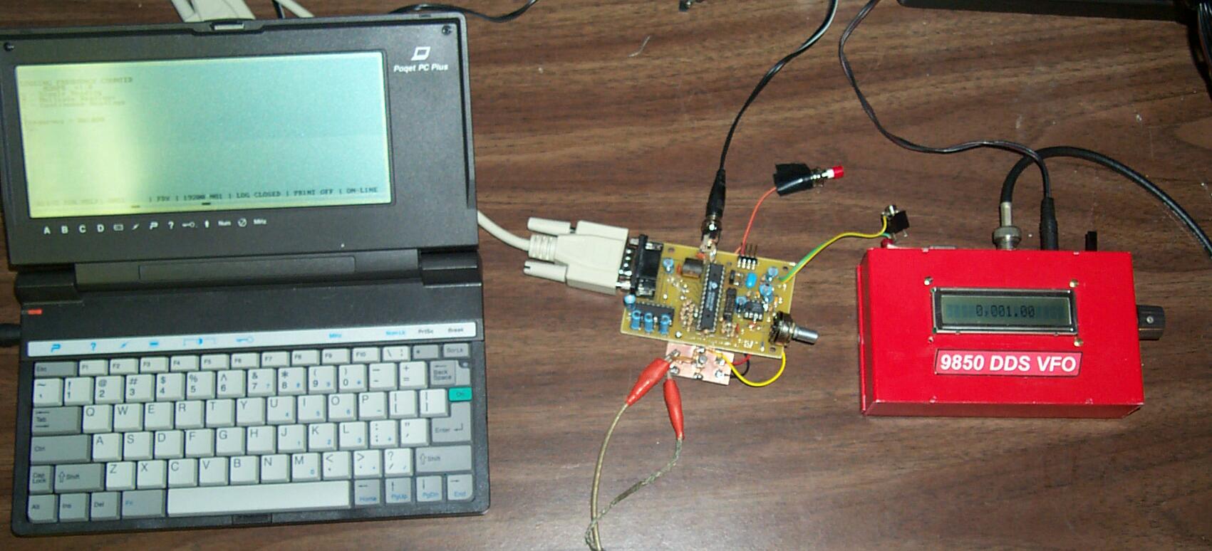
This first photo shows the "system" ... a Poqet PC on the left, running Procomm terminal emulator program, connected to the PSK31 Beacon board by means of an RS-232C serial cable. The sock Beacon pcb has the shaper circuit attached at the bottom (shown in greater detail in a photo farther down on this page). One the right is my 9850 DDS VFO serving as an accurate frequency source, feeding the shaper circuit by way of a cable with alligator clip leads. (See related links on this website for the Poqet computer and for the DDS VFO project.)
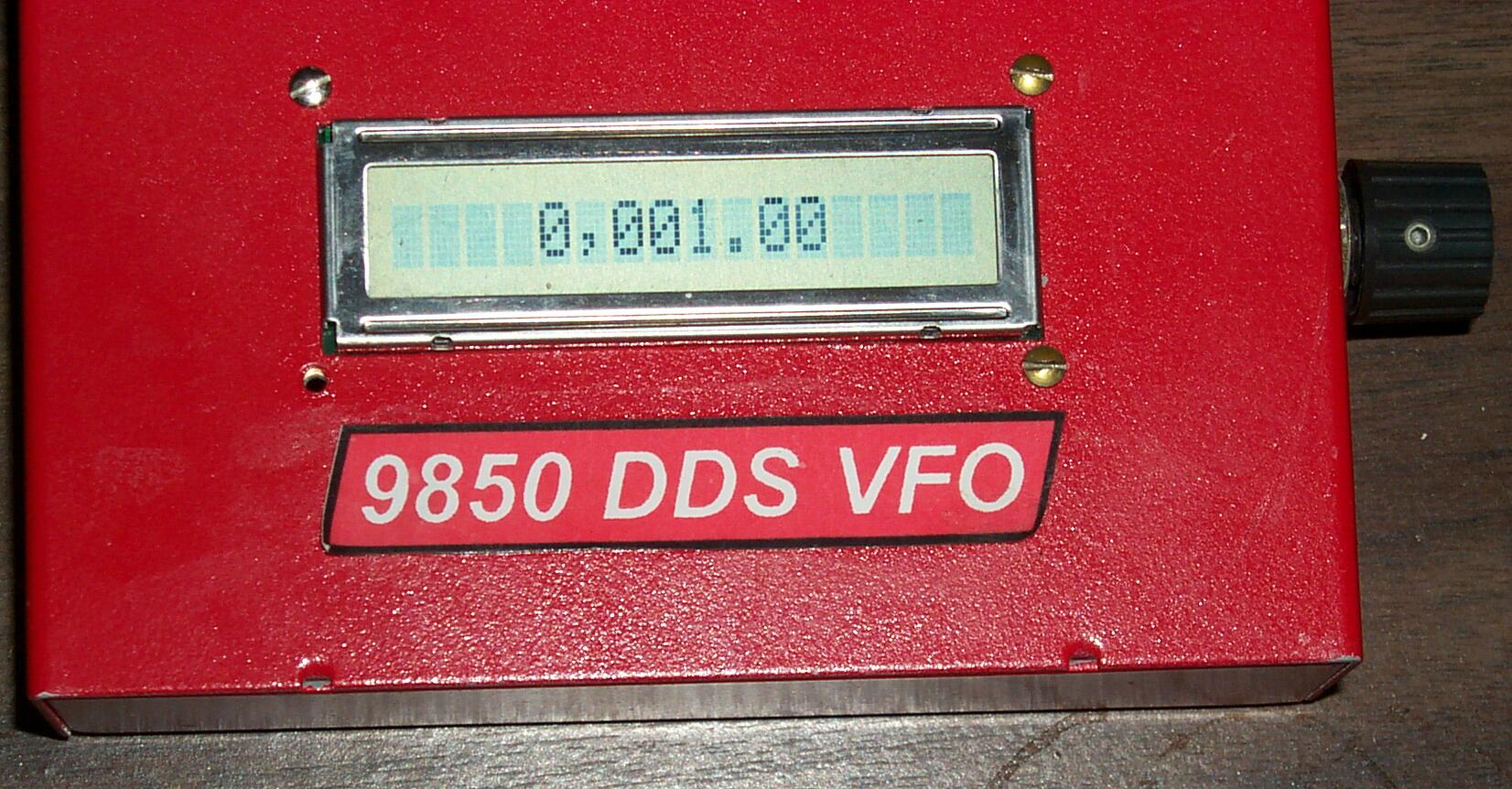
The photo below is a close-up of the 9850 DDS VFO frequency source used to drive and test the Logging Counter project. It is shown dialed to supply a precise 1 kHz signal to the shaper circuit and the Beacon pcb.
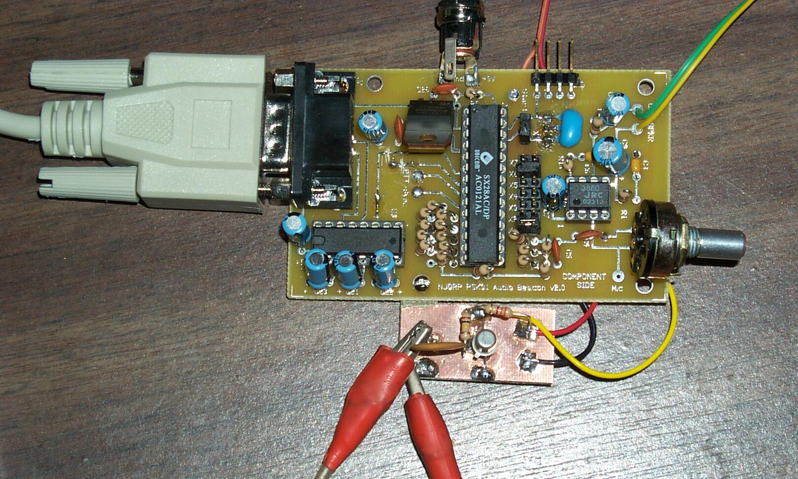
The photo below shows the Beacon pcb with the shaper circuit tacked to the bottom. Per the Shaper Schematic, the connecting wires are tack-soldered to the indicated points on the underside of the pcb, providing power, ground and signal input to the SX microcontroller. The alligator clip leads are providing the known-frequency being supplied by the DDS VFO box.
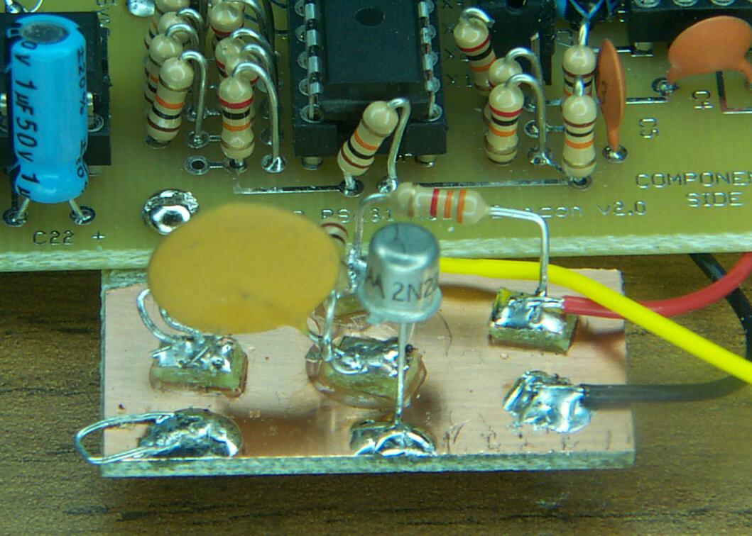
The photo below shows a close-up of the Signal Shaper circuit. It was constructed using Manhattan-style techniques and worked first time tried. I shaped the copper clad board with a little "L" tab jutting out that enabled me to screw it to a nearby hole in the Beacon pc board. Note the wire "loops" on the input pad and ground connections on the let side of the Shaper board. These loops provided convenient clip-on points for my interconnecting cables.
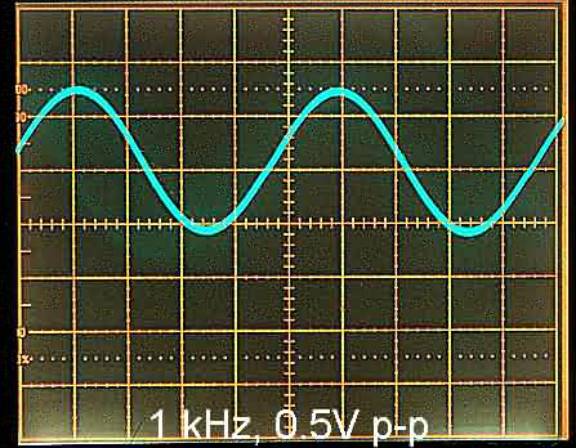
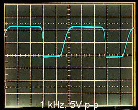
The photos below are of my oscilloscope displaying (on the left) the input 1 kHz sine wave signal coming from the DDS VFO, and (on the right) the corresponding signal coming from the signal shaper circuit. It's not important that the shaper produce a perfect square wave, but only that the edges are relatively vertical, thus providing reliable transitions for the microcontroller to sense and measure the signal period. In our case, we program the controller to be interrupted with every negative transition of the signal, thus using the better edge. Also, notice that the signal shaper provides about a 10x voltage gain, bringing the 0.5Vpp signal of the DDS VFO up to about 5Vpp, making it most effective for measurement by the SX micrcontroller.
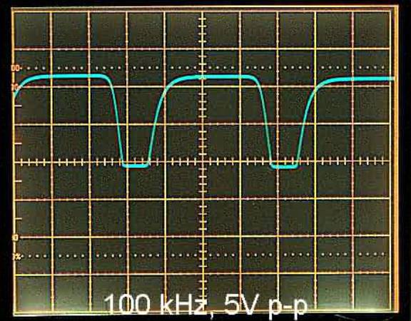
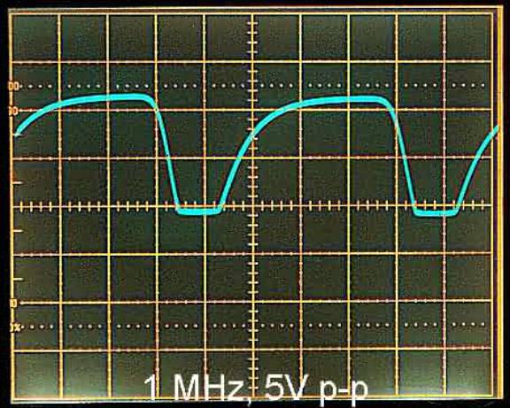
The oscilloscope photos below represent the shaper circuit output for 100 kHz and 1 MHz signals, respectively. Note how the effective R/C time constant of the shaper's input components becomes more noticeable as the frequency increases. The slower-rising edges in the case of the 1 MHz signal are still usable, but it's advisable to change to a smaller valued input coupling capacitor (e.g., .01 uF) for frequencies higher than this. Using smaller valued caps will reduce the time constant and produce steeper edges for the signal being presented to the SX chip for measurement.
![]()
![]()
![]()