 PSK31
Audio Beacon
PSK31
Audio Beacon |
PSK31
Audio Beacon |
|
PSK31 Beacon App #1: Tone Gen PSK31 Beacon |
ORIGINAL PSK31 BEACON PROJECT -- DESCRIPTION
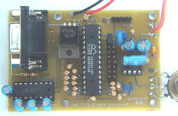
The PSK31 Audio Beacon is an easy, fun and intriguingly useful project that has evolved from an ongoing design effort to reduce the complexity of a PSK31 controller. A conventional PC typically provides the relatively intensive computing power required for PSK31 modulation and demodulation. With this Beacon project, however, the PSK31 modulation computations have been designed to fit into a small PIC-like microcontroller that can serve as the basis for the transmit half of a standalone PSK31 controller. A fast and inexpensive microcontroller has been programmed to generate an audio data stream using the PSK31 algorithms. The data-driven audio waveform is fed to an amplifier IC that drives a speaker - and voila, the familiar and melodious PSK31 warble is able to be heard! When presented as input to a PSK31 receiving system such as DigiPan, these modulated audio tones are decoded and the programmed beacon string is displayed. A keyboard or data terminal may also serve as the input of real-time textual data to the PSK31 Audio Beacon. A standard RS-232 serial interface is provided in the hardware and software to allow a more dynamic "signal generator" use of the project. The project can be electrically connected to the input of an SSB transmitter to create an RF PSK31 beacon. This project is also ideally suited for groups wishing to have some "audio beacon" fun during meetings. A number of club members would operate their audio beacons while someone attempts successful copy of the beacon strings while sitting at a laptop equipped with DigiPan software. Construction is simple and straightforward and youll have immediate feedback on how your Beacon works when you plug in a 9V battery and speaker. Beacon Features
"What Can I Do with a PSK31 Audio Beacon? As mentioned, the Beacon may be used as the basis for a fun group "contest" activity for your club. All contestants would turn their beacons on and gather around a laptop running the DigiPan application. Laptops generally have built-in microphones that would be used to decode the audio PSK31 tones "in the air" ... and with over 100 beacons warbling simultaneously, there will certainly be audio tones in the air! Recall that each Beacons microcontroller is customized with a callsign and is run on slightly different frequencies. One Beacon may have its tones centered at 978 Hz, while another may have its tones at 1050 Hz. This spreading out of Beacon signals will help when multiple beacons are placed in service at the same time within close geographic proximity. Okay, so youve got the picture of a whole bunch of club members amassed around a table with an operator sitting at the laptop running DigiPan, right? Within a specified period of time, the idea is to see how many of the Beacons can be copied (callsign & code word), as captured by DigiPan. Factors involved in successful reception include the settings of the audio amp, the type of speaker, the distance between the Beacon and the laptop, adjacent QRM (other Beaconers), etc. "Points" are awarded to all Beacons for the degree of solid copy captured to the DigiPan log during that 15 minute period. (You can see a photo of this excitement in the "Up Front" section of July QST. The photo was taken at the Atlanticon QRP Forum held last spring.) This all may may sound complex, but its really quite simple build the Beacon, turn it on and see how well it can be copied by DigiPan. Each contestant could actually do this during the test phase at home prior to the club event. Putting the Beacon on the Air Projects can be fun in a group activity, but the PSK31 Audio Beacon has lasting value for the PSK31 enthusiast. The audio tones generated by the Beacon can be presented as input to any SSB transmitter a Warbler, PSK-20, PSK-40, or even a Yaesu FT-1000MP. Thus, a PSKer can easily put a beacon signal on the air for all the same reasons that CW beacons are used (e.g., studies of propagation, power levels, antenna characteristics, etc.) Special care must be exercised on two counts, however. First, the audio level driving an SSB transmitter needs to be extremely low compared to the output levels provided by the Beacon Kit. Most certainly, the LM386 audio amplifier output that drives the Beacons speaker should not be used when feeding a transmitter. One should take the output of the R-2R DAC and put it through a voltage divider pad (or potentiometer) to bring the 0-to-4.5V sine wave signals down to the millivolt range required by an SSB transmitter. The lower the better! If the transmitter is over-driven, all sorts of problems occur with the transmitted RF spectrum terrible IMD, distortion, and interference to other signals up and down the band. You will quickly learn the wrath of others seeing your callsign and email address transmitted over and over. Secondly, even in the case of perfect signal quality, very careful attended operation needs to be done when using this Beacon project with an RF transmitter. There should be no interference whatsoever to any other communication on the band, and even while in the CONTINUOUS mode of operation, the Beacon should be stopped periodically to determine if other signals are present. Never leave the beacon on for continuous, unattended operation! Unattended beacon operation is illegal in the FCCs eyes, and you would not be able to determine if other signals are present in the area of you transmissions.
Page last modified:
November 28, 2001
|