![]()
Back to the Future
The NorCal Herring Aid 5
by Glenn Torr, VK1FB
![]()
glentorr@ozemail.com.au
This article describes changes made to the "Herring-Aid Five" receiver presented by Jay Rusgrove, then WA1LNQ, in the July 1976 issue of QST to allow the design to be duplicated with readily available components. The original circuit was designed so that the constructor could obtain all the parts from Radio Shack and many of these parts are no longer available.
In keeping with the theme of using food containers as chassis for these designs this receiver was built onto an oval shaped Scottish Herring can hence the name. Construction was similar in general layout to the Tuna Tin 2.
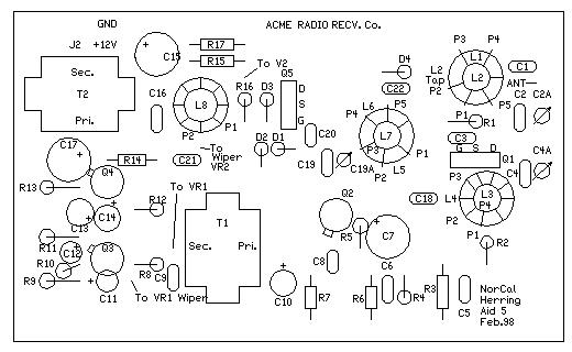
The first change necessary was to get a PCB which suited the new component foot prints and allowed for changes to the circuit where needed, to this end Doug Hendricks, KI6DS, laid out a new PCB using CirCad. Prototypes of this board were generated by Gary Diana, N2JGU. The new board is rectangular which will allow the constructor more flexibility in the choice of chassis or enclosure. Refer to the board layout.
The parts substitutions were made in such a way as to have as little impact on the original design as possible. The main changes have involved the substitution of toroids for the original solenoid style inductors. This then lead to the addition of trimmer capacitors, as inductance adjustment was no longer practical by squeezing up or stretching out turns. Audio transformers T1 and T2 were replaced with readily available equivalents as were the semiconductors.
The Receiver
This receiver is a "minimal" direct conversion design in which the designer has traded a little performance for ease of construction with the then widely available components. I think the most unusual part of this receiver is the use of a single unbalanced BJT as the mixer in a 40 meter receiver, I imagine this unusual choice would cause severe problems where broadcast station interference was present. As the designer of the original receiver noted audio bandwidth was left wide enough to allow for the reception of SSB and AM signals. The up side of this is that it allows for the use of the receiver for these modes, the downside is that it compromises the receiver's CW performance.
The Circuit
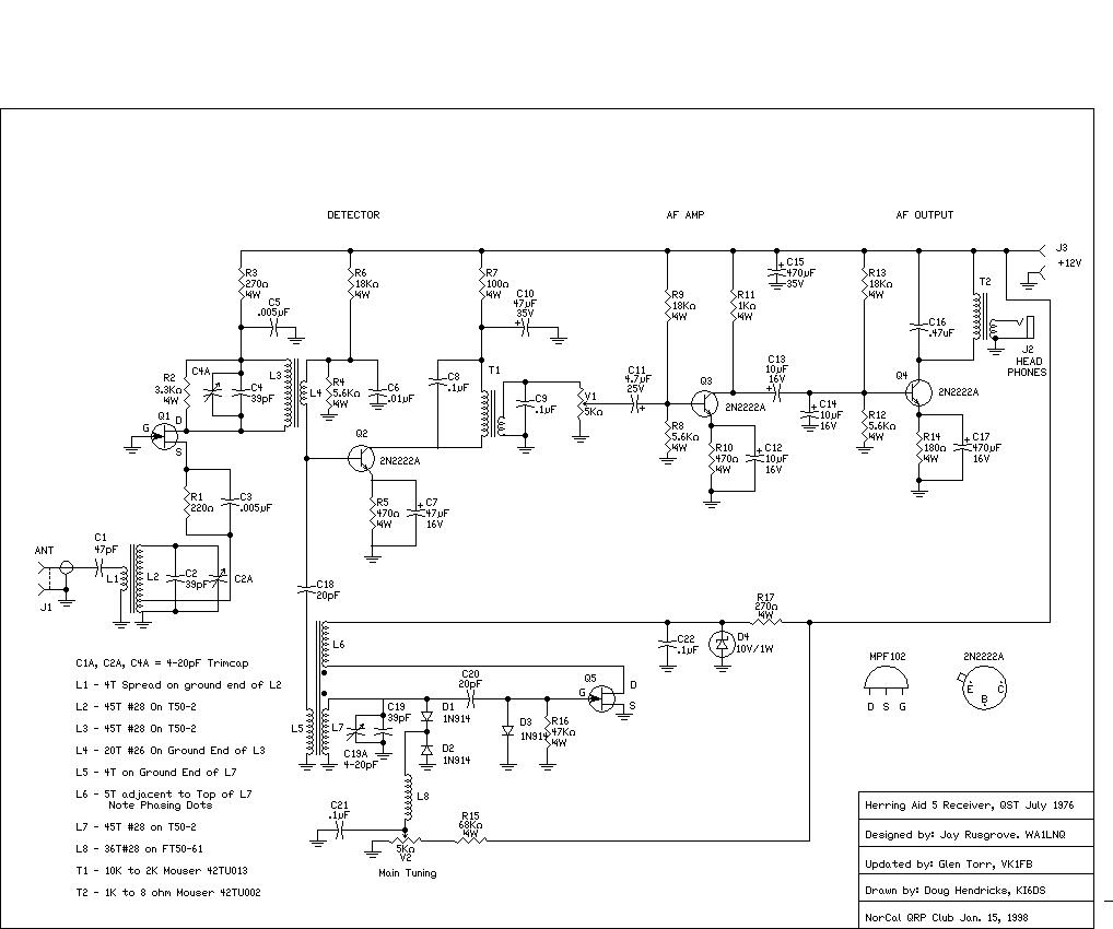
Refer to the Herring Aid 5 schematic. The incoming 40-meter signal is coupled to the source of Q1 via a tuned circuit consisting of L1, L2, TC1 and C1. Q1 is a grounded gate RF amplifier and has its source tapped down L2 to preserve the Q of that tuned circuit. The output of the RF amplifier is coupled to the Mixer by another tuned circuit consisting of C2, TC2, L3 and L4. These tuned circuits provide all of the 7 MHz selectivity. Q2 then mixes the VFO with the incoming RF and the resultant Audio signal is amplified by Q2 and coupled by T1 to the audio gain control. Q3 and Q4 are conventional common emitter audio amplifier stages; the audio output is coupled to low impedance phones by T2. The VFO consists of Q5, which operates as an un-buffered voltage tuned VFO. Ordinary silicon diodes such as 1N4148 are used as varactor diodes in this circuit. The tuning pot provides a voltage variable from 0 to approximately 800 mV, which allows the oscillator to tune approximately 100 kHz at 7 MHz.
Construction
Note: The description by Doug, KI6DS and Dave, AD6AY of their debugging of an early prototype which appears on the NorCal page is invaluable companion reading to this section.
I commenced by building and adjusting the VFO. The VFO was designed to cover a range of any 100 kHz of 40 Meters for 180 degrees of rotation of the tuning potentiometer, which suits the vernier drive originally, used. I first wound L7 which consists of 45 turns occupying about five-sixths of the T-50-2 toroid. L6 consists of 5 turns immediately adjacent to the top of L7 and noting the phasing in the circuit. L5 consists of 4 turns over the ground end of L7.
VFO output with the pot at the low frequency position (ground) is fairly low so as only 180 degrees of pot travel is used I set the pot to about 20 degrees up from ground and then adjusted the frequency to be 7.000 MHz with TC3 (across C4). If necessary a turn or two can be added to or deleted from L7 to achieve the desired range, it may be easier to replace the relevant capacitor, C19, with a slightly different value. This gave my receiver a range of 7.000 to 7.100 MHz. If the oscillator does not oscillate try reversing the terminations of L6.
The 180 degree requirement can be addressed either by using a vernier drive similar to the original or constructing a frequency scale with 7.000 MHz at 9 o'clock, 7.050 MHz at 12 o'clock and 7.100 MHz at 3 o'clock and simply ignoring the unused portion of the tuning pots travel.
The rest of the receiver can now be constructed. L2 consists of 45T on a T-50-2 toroid, tapped up 5 turns from ground; L1 consists of 4 turns over the ground end of L2. L3 consists of 45T on a T-50-2 toroid with L4 consisting of 20 turns across L3. When completed C2A and C4A can be adjusted for best signal strength using live signals or an appropriate signal source such as a 40-meter QRP transmitter into a dummy load. C2A and C4A should each allow 2 peaks in incoming signal level per 360-degree rotation of the trimmer. If only one peak is obtained it may be necessary to add a turn or two (if the peak corresponds the plates fully meshed) or remove a turn or two if the peak corresponds to the capacitor plates fully unmeshed. Alternatively it may be easier to increase or reduce (respectively) C2 and C4.
Performance
The performance of the Herring-Aid Five is better than I expected however it has some limitations due to the earlier mentioned design tradeoffs. Additionally the receiver is able to copy SSB signals; this is a useful feature for the beginner but is a limitation when using CW. I have been unable to find Scottish Herrings in VK and in any case I prefer to build this type of equipment on a wooden base with a front panel for the controls so that I can see and play with the circuit at any time
Conclusion
This receiver offers a number of attractions. It allows you to experience the performance of the humble single BJT mixer. Nothing is hidden in IC's; all voltages are available for observation. It provides a platform to experiment with one circuit block while leaving the others constant. The effect of a modification is more clearly seen e.g. a high gain IC audio amplifier could be constructed outboard and audio fed to it from the audio gain pot to observe the benefit or otherwise of higher audio gain on overall performance.
I have made numerous decisions and assumptions in converting this design to modern parts and have not explained these decisions in any detail. Please feel free to contact me with any suggestions, questions or observations. I am not an expert but rather a keen learner and I make no claim that modifications I have made are the ultimate. I have enjoyed "playing" with this circuit and believe there is a lot of fun to be had "Back in the Future."
I would like to thank Jay Rusgrove for the fine original design and article, Doug Hendricks, KI6DS, for his tireless work in laying out the PCB and co-ordinating the project, Gary Diana, N2JGU, for prototyping the PCB, Dave Fifield, AD6AY for his work with Doug on one of the prototypes and his suggested improvement to L4 and finally Doug DeMaw, W1FB (SK) for giving us so much.
72, Glen Torr VK1FB
![]()
| 3 | C2A,4A,19A | 4-20pF Trimcap |
| 2 | C18, C20 | 20pF |
| 2 | C2, C4, C19 | 39pF SM |
| 1 | C1 | 47pF Disc |
| 2 | C3,5 | .005 uF |
| 1 | C6 | .01 uF |
| 4 | C8,9,21,22 | .1 uF |
| 1 | C11 | 4.7uF/25V Elec. |
| 3 | C12,13,14 | 10uF/16V Elec. |
| 1 | C7 | 47uF/35V Elec. |
| 2 | C15,17 | 470uF/35V Elec. |
| 1 | C16 | .47uF |
| 1 | D4 | 10V/1W Zener |
| 3 | D1,2,3 | 1N914/1N4148 |
| 3 | L2,4,7 | T50-2 |
| 1 | L8 | FT50-61 |
| 2 | Q1,5 | MPF102 |
| 3 | Q2,3,4 | 2N2222A |
| 1 | R7 | 100 ohm |
| 1 | R14 | 180 ohm |
| 1 | R1 | 220 ohm |
| 2 | R3,17 | 270 ohm |
| 2 | R5,R10 | 470 ohm |
| 1 | R11 | 1K |
| 1 | R2 | 3.3K |
| 3 | R4,8,12 | 5.6K |
| 3 | R6,9,13 | 18K |
| 1 | R16 | 47K |
| 1 | R15 | 68K |
| 1 | T1 | 10K-2K Transfmr., Mouser 42TU002 or 42TM002 |
| 1 | T2 | 1K-8ohm Transfmr., Mouser 42TU013 or 42TM013 |
| 2 | VR1,2 | 5K Pot |
Misc. Connectors for headphones, power and antenna, knobs, case, stranded hookup wire. Circuit boards for this project are available from FAR Circuits, 18N640 Field Court, Dundee, IL 60118. The cost is $7.50 per board plus $1.50 S&H for up to 4 boards. Order the NorCal Herring Aid 5 Receiver Board.
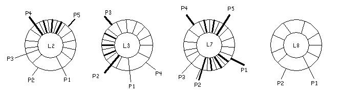
Preparing the Coils
Please see the coil winding diagram for information on winding the coils. They must be wound in the "same direction or sense". Note that the following information applies to each coil.
Coil L2:
Coil L3:
Coil L7:
Coil L8:
![]()
Troubleshooting the Herring Aid 5
by Doug Hendricks, KI6DS
I finished the Herring Aid 5 prototype on the board that Gary Diana made for me on a Thursday night. Plugged in the power, hooked up the antenna, put the headphones on and expected to hear that wonderful hissing sound that you expect from a receiver. Nada, nothing!! Egads, it doesn't work. I looked at the parts, check it twice, checked the toroid connections, but alas, nothing helped. What to do?? I called Dave Fifield, trouble shooter extroidinaire and a good friend. I asked him if he would have time to look at the rig if I were to drive over to San Jose. Dave is a good friend and can't say no, so he said sure come on over, but it had to be about 4 PM or so on Sunday as he had a huge list of honeydo's to finish for the XYL.
With that in mind, I packed up the board, the schematic, the layout, the parts placement drawing and the original article and drove the 125 miles one way to Dave's house. (One advantage to having lived in western Kansas, distances don't mean a lot. Ask anyone who has lived in west Texas, the Oklahoma Panhandle or anywhere out west. We are used to driving.) When I arrived Dave greeted me at the door and we sat out to debug the receiver (Dave doing the work, I was watching and listening as he very patiently explained what he was doing and why).
One problem we had was this was a new layout, done by me, and it was not tested. I watched as the old master himself went to work. He told me that he was going to use the "Paul Harden, NA5N" method. He would start at one end of the schematic and check each section. I sat down and watched as Dave did the following.
First of all he checked for 12 volts at the supply and then for 9.1 volts on Q5. (The schematic calls for a 10V zener in series with a 270 ohm resistor, but Dave had suggested using a 9.1V zener in series with a 390 ohm resistor over the phone when I couldn't find a 10V zener.) Had the 12 volts at the supply, but oops, there was only 1 volt or so at the drain of Q5, which is the FET in the VFO. Dave turned to me and said, this is not good, we must have 9 volts or so. Something is loading down the circuit. He then checked the layout against the schematic, R16, D3, C22, R17 and D4 were all soldered in correctly and in the proper position. Dave had a bewildered look and asked where I had gotten the transistor. I replied that it came from my stash, but it was not the MPF102 called for but rather a J310. (I thought they were interchangeable, and as I was soon to find out, they are not always.) Dave replaced the J310 with an MFP102 and bingo, 9.1 volts, just as it should be.
Next he said that we would see if the VFO was VFOing. He hooked up the scope, and nothing, not a sine wave in sight. He looked at the circuit, checked all the parts and determined that the coil was wound out of phase, so he reversed the leads for L6, and again, like magic, bingo we had an oscillator. He measured the frequency, and it was at 6.8 MHz, which was a little low. It was easier to lower the capacitance in the circuit by changing a cap than it was to change the turns on the toroid, so Dave replaced a 39 pF with 5 pF and we measured the high end. Oops, now it was at 11.2 MHz for the high end. He looked at me, and I know that he knew, but he asked what value we should try next. I suggested 22pF as it was in between the two values that we tried. He soldered it in and voila, the top end was about 7.8 MHz and using trimcap C19A he was able to set the bottom of the tuning range at 6.998 MHz, which was close enough for us. One thing, the 5 pF that we tried first was a regular disc ceramic, it drifted several hertz per minute, but when he replaced it with a 22 pF Silver Mica, the vfo was much more stable. The point is use NPO's, Silver Micas or Polystyrene's in VFO's not 20% disc ceramics.
Ahhh, now we had a vfo, and Dave hooked up the signal generator at 7.040 MHz and he listened for it. It was there!! But weak, very weak. The mds of the receiver was only at -80dB, not very good. Lousy in fact. Dave said not to worry, that we had some tweaking to do. The circuit has two tuned circuits that need to be peaked and are set by peaking a trimcap in each circuit (C2A and C4A). The first one came up very nice with two peaks, which is what you are looking for when you use a trimcap. Bruce Florip wrote a nice article on this in a past issue of QRPp. But the other one only had one peak. Dave explained that this meant that the circuit was not reasonat at 7MHz. So he tried removing capacitance (again much easier than adding or removing turns) and it worked. Soon he had two peaks in the adjustment. He adjusted both of them back and forth, as they were interactive. Finally he was satisfied. Now, lets see what it does. Only -100 dB of mds. Terrible. Dave read the original article and saw that Jay Rusgrove got an mds of -130 dB!! Something was wrong.
Dave looked at the circuit, and then he asked about the transformers.
Were they the same? No one was a 10K to 2K and the other was a 1K to 8 ohm. He checked them out for proper placement of the primary and secondary and they were correct. Then he asked if I was positive that I put the right transformer in the right place on the board. I wasn't so we checked the part numbers with a Mouser catalog, and sure enough, I had reversed them on the board.
Dave had me repeat after him, "Doug, I am a dummy. Doug, I am a dummy." That is supposed to exorcise the dummy demons or the badgers or something. Dave unsoldered the parts, exchanged them and tested the rig. Maybe -110 dB. But still something was wrong. Then Dave looked at the bias resistors on the 3 2N2222 transistors and he said, "Ah Hah! I see the problem." One of the bias resistors was 560 ohms instead of 5.6K, it does make a difference. He switched it out, and tested the receiver. He still wasn't satisfied. Then he sat down and studied the schematic. He decided that we weren't getting enough coupling at L3 and L4. This was one of the coils that was changed from the original Radio Shack modified part to a toroid. He rewound it and changed it from L3 at 45 Turns and L4 at 5 turns to L3 at 45 turns and L4 at 20 turns. He resoldered the toroid, and what a difference. Dave tested the mds, and it was at -123 or so. Very good for such a simple receiver. The rig works!! Thanks to Dave for doing such a neat job, and helping me to learn some more about trouble shooting.
72,
Doug, KI6DS
Return to the "Back to the Future" page
![]()
![]()
![]()
![]()