
NJQRP
Sniffer
CONSTRUCTION
TIPS
Answers to some common questions that have come in ...
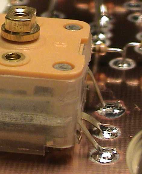
1)
I'm confused about which
leads of C1 (the variable tuning capacitor) should be used.
First,
snip off the leads from the side the capacitor containing 4 leads
You
will USE the leads coming from the side of the capacitor containing 5 leads, as
shown below. Nip off the bottom left and bottom right leads, and use the
remaining three leads (marked as 1, 2 and 3). Lead #2 is the common point
between the dual internally-ganged capacitors and should be connected to L2, C2
and the antennas, as indicated in the schematic.
2) Looking at the
Parts Layout template in the directions, I see a number of places where
it seems as if two or more components are tied together, but have separate pads.
For example, at the junction of R12, LED-1, M1 and D3, it would be possible
for them to meet at a common point, but three pads are used. Is this just to
make the layout prettier, or more open? Do you use a small jumper wire to
connect them?
Yes, "multiple pads tied together" are
used primarily to help the builder by having a more open layout. A
purist (with a steady hand) could indeed reduce the pad count and have a more
compact layout. But a greater chance of success exists with a more open
layout as suggested. (And don't forget that this was just my personal
suggestion for a layout ... use whatever layout or configuration makes you
comfortable!)
3) The Layout
template also shows pads being used for places where the component lead goes
to ground. Wouldn't these leads just get soldered to the ground plane, with no
pad?
Yes. I've found the approach of using a pad even
for grounded leads is convenient in that it allows me later to easily
"lift" the component from ground should I need to add another in
series or perhaps to measure the current through that lead to ground.
Again, builder's preference!
4) I got the
Islander Pad Cutter and I'm ready to start making the pads. Do I have to
use a drill press like the instruction sheets with the Pad Cutter suggests?
You'll have the best success in using the Pad
Cutter if you can hold it steady and at 90-degrees to the plane of the
copper-clad board being cut. I usually chuck the Pad Cutter into a small
drill press (e.g., $65 from Home Depot) and lay the board flat on the plate
just inches beneath the end of the cutter. I'm then able to drill all
the pads in the copper-clad within 5 minutes merely by working the
fast-turning bit down and up for each of the locations. I've also
successfully used the Pad Cutter when chucked up in a Dremel hobby tool, using its
$10 "drill stand" accessory that I picked up at a local hardware
store. Again, the key to success in using the Pad Cutter is to use high
speed and to use it at 90-degrees to the board being cut.
5) Do I have to
use the Pad Cutter to make the Manhattan-style circuit nodes in the Sniffer
Kit?
No, you could easily nip off small pieces of the
thin copper-clad strips supplied in the kit to make standard little
rectangular pads that you'd Super-Glue to the surface of the copper-clad
board. Then just solder the component leads to the pads as described in the
Construction section of the manual.
6) How did you
hold the 9V battery down in your prototype Sniffer?
I drilled holes in the copper-clad board on each
side of the outline for the battery. Then I used two Tie-Wraps ganged together
(to get the required length) to go around the battery and through the holes in
the board. They are pulled tight and joined bottom side of the board.
This is a neat technique in that the Tie-Warps hold the battery tight enough,
yet they allow the battery to be slipped out for replacement. (Or during
travel, as I found out ... the TSA agents at the airport certainly didn't like the
Sniffer in my carryon!)
7) I broke one of
the germanium diodes and had to use a replacement from my junk box, but found
that I couldn't get the unit to operate correctly. The meter couldn't be
zeroed with the balance trim pot. Yet I tried another diode and it
worked okay. What's happening?
The diodes supplied in the kit are all from the
same "batch" and their junction characteristics are all pretty
close, as they need to be when used in a bridge configuration as in the
Sniffer. When the junction characteristics vary greatly (i.e., if their
forward voltage drops are significantly different), the trim pot may not have
enough adjustable range to balance out the bridge and a uncorrectable plus or
minus offset will be seen in the meter reading. The same condition could
also conceivably happen with the two red LEDs. A simple check of forward
voltage drop for any replacements diode could be done to ensure that it's in
the same ballpark at the one already being used. You don't need to be
too concerned about having a "precisely matched pair" of diodes, as
the design is not that sensitive.
8) I saw someplace
that when you lay toroidal inductors close against a ground plane, the circuit
performance is affected. Yet the photo of your Sniffer on the website
shows them laying flat on the copper-clad. What's sacrificed by mounting
them this way.
You're right. When mounted this way the
tuned circuit's Q is lowered, making the circuit less sensitive and less
selective. Although the Sniffer worked pretty well as-is, it might even
be better if I were to peel away the copper-clad material underneath the
toroids, or perhaps mount the toroids in a "stand-up" manner.
Even better yet, a Sniffer seen at a recent NJQRP meeting had them glued right
to the side of the polyvaricon tuning capacitor C1, providing nice short leads
and a solid, non-metallic mounting surface. Builder's choice!


Last Modified: July 18, 2003