

#21 . . . PC Dots for RF Breadboarding
![]()
by Joe Everhart, N2CX
Anybody who does much homebrewing has their favorite methods of breadboarding. I use a variety of them myself, including Vector (tm) board, "ugly style" and Ball O'Components. My favorite bears some similarity to the W7ZOI "ugly style" though I learned it from a ham buddy 20+ years ago. I call it PC dots construction.
Like ugly style, it uses a piece of copper clad printed circuit board as a ground plane and mounting base. The continuous ground plane makes it ideal for RF circuits, where good grounding and short lead lengths are important. But where ugly style uses high value resistors soldered upright on the base plate for tie points, PC dots uses small round pieces of copper clad PC board for component attachment.
The dots are simply PC board material punched out of scrap material. I use a hand punch with a 1/4 inch die to fabricate the dots. They are punched out copper side up so that the convex "dome" is upward and the concave side is downward. The tool is a simple hand punch available by mail order for less than $30.00 from Harbor Freight. Their part number is 35510-OBHA and you can reach them by phone at 1-800-423-2567. (I have no connection with this company other than being a satisfied customer.) By the way, the punch is also quite handy for punching out round holes in metal chassis for permanent homebrew projects and ideal for making clean holes in the thin metal of the popular Altoids (tm) mint tins.
The pads are secured to the ground plane by putting a dot of cyanoacrylate "super glue" on the plane and pressing the dot in place. When the glue sets, the dot is held firmly where you want it. Of course the copper surface should be free from oxidation and and surface contamminants for the glue to hold and for good solderability. If you ever want to move a dot, simply use a screwdriver and smack it sideways. Super glue has great tensile strength but very little shear strength.
Components are simply soldered to the dots, which serve as junction points. Ground connections are made by soldering right to the ground plane. A side view of component connection and grounding is shown in Figure 1. The technique is very good for discrete components, although somewhat awkward for integrated circuits. For DIP IC's, I use an etched pattern on a separate scrap of PC board material like the one used in Figure 2. The extra board is held onto the ground plane by by soldering wires on the copper areas at the ends, then soldering those wires onto the ground plane.
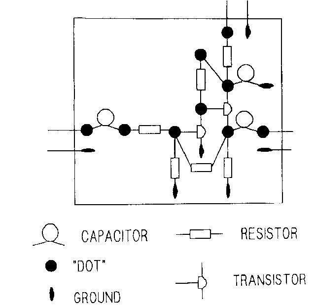
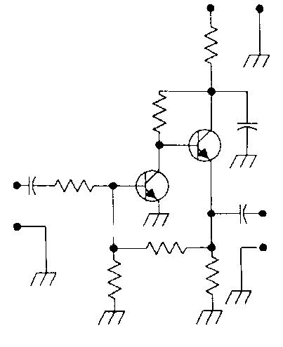
Making up a breadboard with dots is very fast! You just start with a schematic diagram and lay out the dots and components as you go along. You might say it is free-style breadboarding. An example of this is illustrated in Figure 4, which is a dots layout for the circuit of Figure 3. You can easily see the one-to-one correspondence between the figures. The circuit shown is a handy RF buffer amplifier used in many W7ZOI projects. For component values, refer to te ARRL publication "Solid State Design for the Radio Amateur" by Wes Hayward and Doug DeMaw.
The ability to place components just where you want them and to get very short connections to a solid ground plane make the dots method very good for RF circuits. Instability caused by long lead lengths and poor grounding are happily absent. The dots do have a stray capacitance of several picofarads to ground, but it should have little effect at HF and VHF. The very first circuit I breadboarded this way was a low noise JFET cascode preamp for 10 MHz. Since then I've built dozens of amplifiers, mixers, crystal oscillators and even a few QRP transmitters using dots.
Using dots lets you make fast breadboards for RF circuits or anything else with discrete components that needs a good ground plane and a flexible means of laying out a circuit.
You can contact Joe at n2cx@voicenet.com or send mail to: Joe Everhart, 214 New Jersey Road, Brooklawn, NJ 08030
![]()
![]()
![]()
![]()