Full-color, full-resolution graphics from the pages of QRP Homebrewer
QHB #8 -- April 2002
|
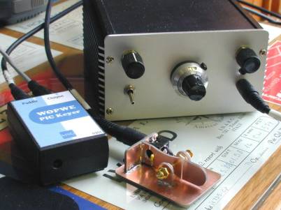
A Manhattan-Built SST Transceiver, by Jerry Hall, W0PWE |
|
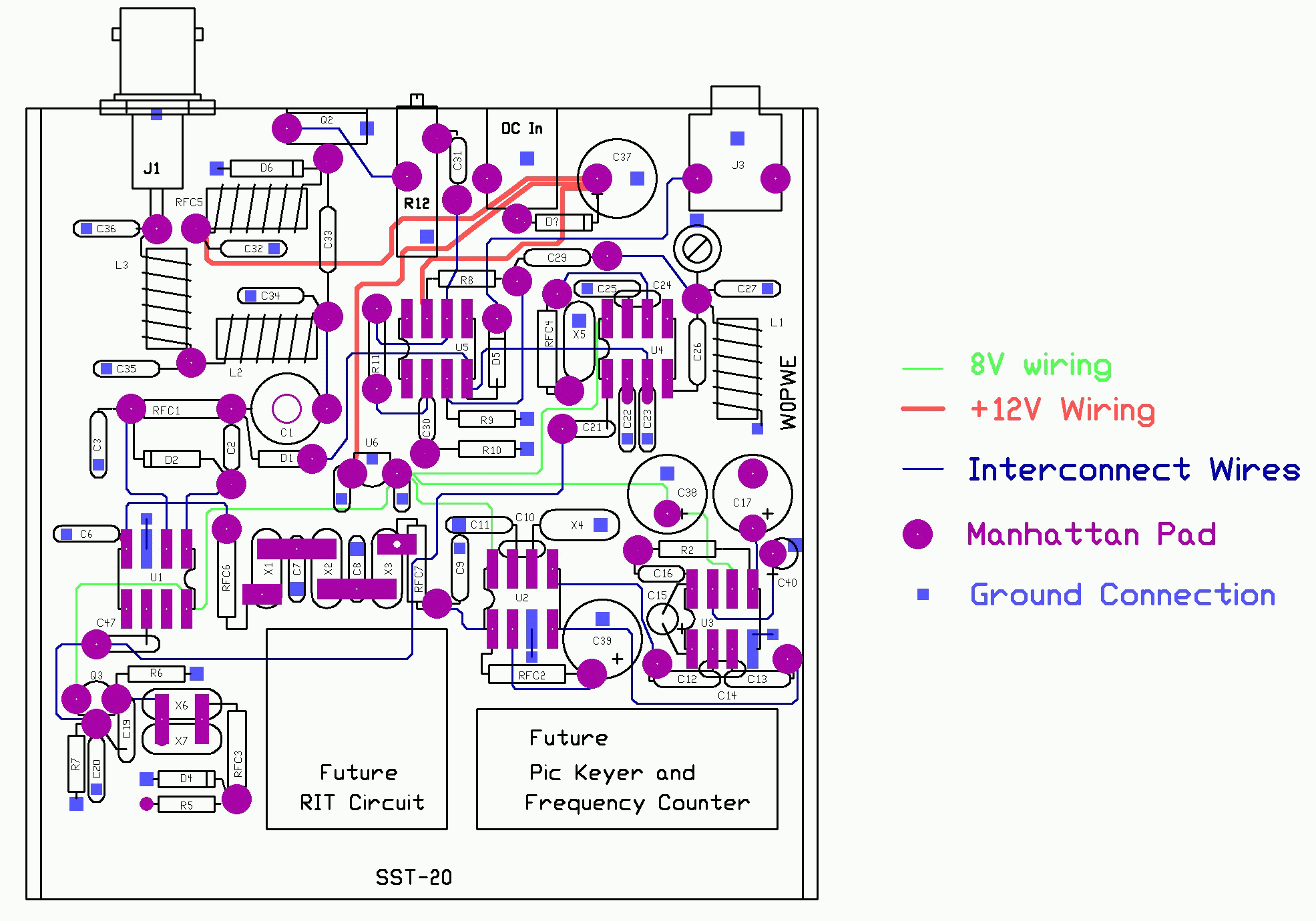
Click image to view full-res GIF file FIGURE 2: Manhattan Layout for the SST.
Large dots are Manhattan pads. Small dots are ground connections. Large
lines indicate +12V wiring. Smaller lines are component interconnect
wiring. |
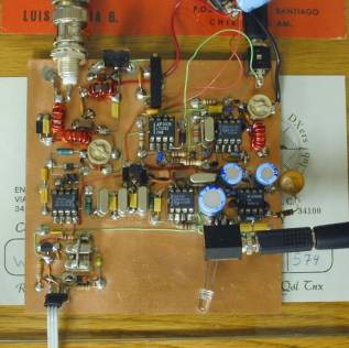
FIGURE 3: SST functional and on the air. |
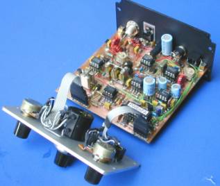
FIGURE 4: Finished SST-20. |
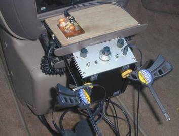
FIGURE 5: SST mobile |
![]()
![]()
![]()