Full-color, full-resolution graphics from the pages of QRP Homebrewer
QHB #8 -- April 2002
|
The Re-Pete Tuner, by Fred Bonavita, K5QLF |
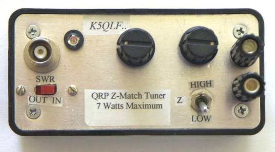
FIGURE 1: Completed ATU. The SWR circuit
LED is to the right of the BNC input connector, and the binding posts for
the balanced line output are at far right. |
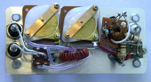
FIGURE2: The bottom side of the aluminum
panel shows the SWR circuit mounted at the right, the high-low impedance
switch mounted at the lower left and L1, L2 and L3 are located in the
bottom center. |
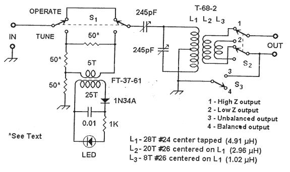
FIGURE3: ZM-40 SWR Bridge and ATU
Schematic |
![]()
![]()
![]()