Full-color, full-resolution graphics from the pages of QRP Homebrewer
QHB #10 -- April 2003
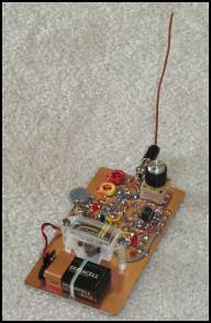
| The NJQRP "Sniffer" Field Strength Meter, by J. Everhart, N2CX and G. Heron, N2APB |
|
|
|
|
|
|
|
|
|
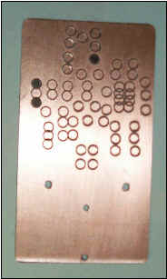
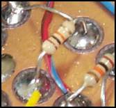
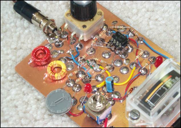
Heres one idea of a layout for the board. The white circles represent pads. As indicated in the text, this just happens to be my layout yours could be entirely different, more ergonomic, and better performing for you. Be ingenious and come up with your own version! And how about an enclosure?!
|
|
|
|
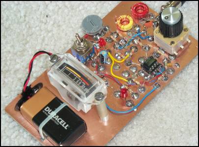
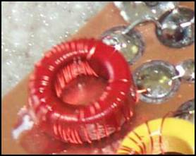
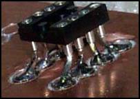
Manhattan-style base board, 3 x 6
with
island pads cut with NJQRP
Islander Pad Cutter.
(Standard PC dots could also be
glued on for pads.)
|
|
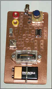
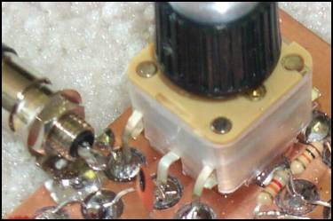
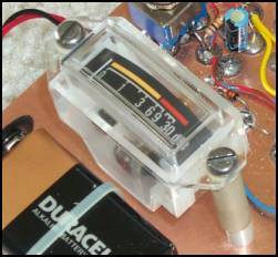
Partially assembled Sniffer
|
|
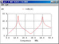
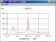
Simulation plots showing selectivity of
front end
|
Table of frequencies covered in tuning
range.
|
|
|
|
|
|
|
|
|
|
|
|
|
|
|
|
|
|
|
|
|
![]()
![]()
![]()