Full-color, full-resolution graphics from the pages of QRP Homebrewer
QHB #10 -- April 2003
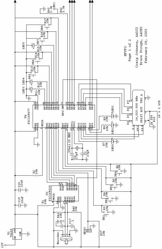
| High-Performance HF VFO using the AD9854 DDS Chip, by Craig Johnson, AA0ZZ |
Figure 1: HF VFO Block Diagram |
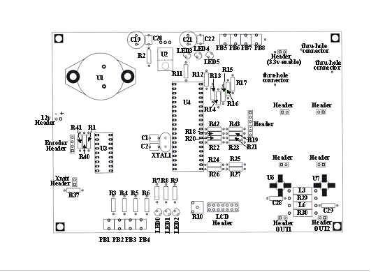
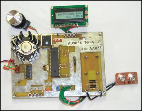 PCB Top: Power regulators (upper left), PIC #1 for shaft encoder (left), PIC #2 for VFO control (middle), control pushbuttons (top & bottom) and status LEDs (top). [Proto PCB shown Production version has solder mask and silkscreened component lengends.] |
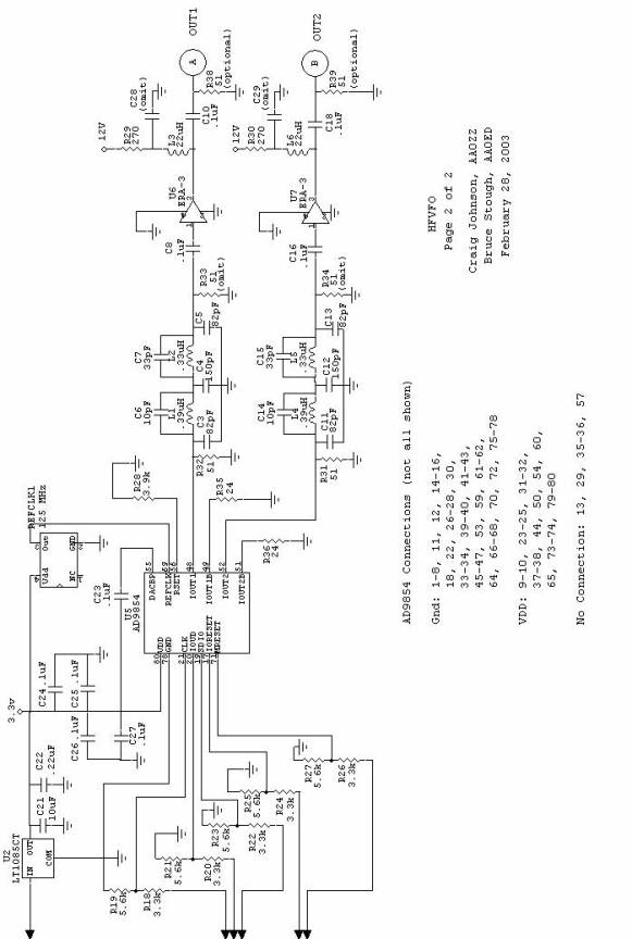
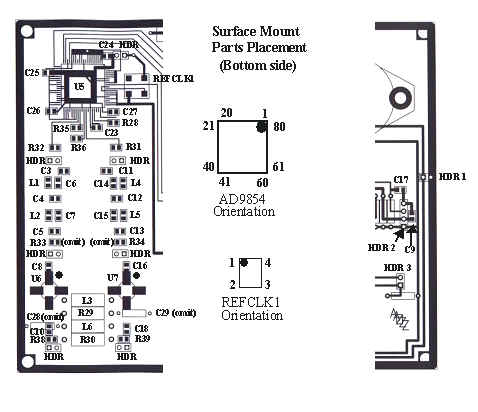
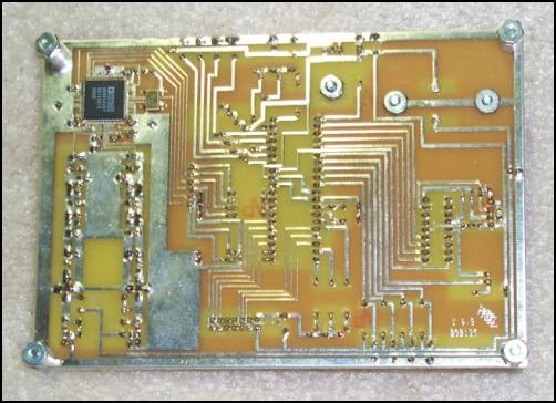 PCB Bottom: AD9854 surface mount DDS integrated circuit |
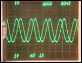 I and Q outputs with 90 degree phase shift |
 |
 |
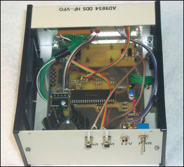 |
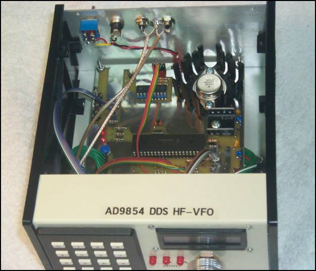 This inside view of the enclosure shows the HF VFO pc board to be a tight fit front-to-rear, but cable to the controls, display and connectors is easily accomplished above the board. The panel-mounted pushbuttons and LEDs are wired in parallel with their board-mounted counterparts. |
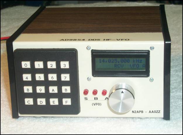
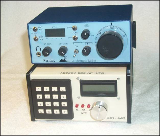 Heres the front view of the stacked pair: the Wilderness Radio Sierra QRP transceiver (top) and the AA0ZZ 9850 High Performance HF VFO (bottom). During operation, frequency tuning is done (and displayed) on the external HF VFO, while the dial and display on the Sierra is not used. |
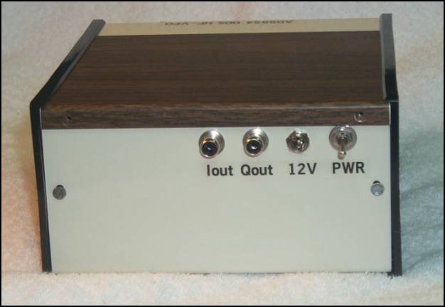
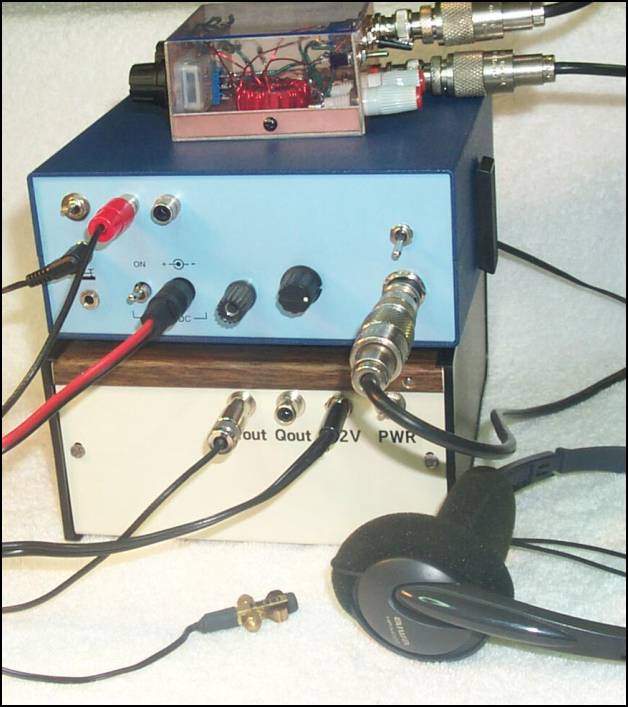 Heres the rear panel interconnections between the HF VFO and the Sierra QRP transceiver. This is a common operational setup used at the N2APB portable station with the NorCal BLT ATU on top, Sierra QRP Transceiver in the middle, and the HF VFO on the bottom. The headphones and small portable paddle are in the foreground, while the power supply (batteries) and antenna cable lead out of the photo. The Sierra was modified to accept an external VFO input that serves as the LO for the rig. |
|
|
|
|
|
![]()
![]()
![]()