![]()

![]()
[Editor's note: You can view the document (below) or download the original Word v6 document to your system.]
Introduction
We had a lot for fun putting this little rig together! It is a very forgiving design that invites experimentation. If ever there was a project that could be recommended as a club activity, this is it!!! This design has the potential to proliferate by the hundreds across the country .
The assembly notes for this project offer a perspective on the transceiver’s flexibility of design and functionality. The notes were written to provide continuity for repairs and/or changes to address the 20, 40, and 80 meter bands in future projects.
The band of choice for this rig was the 30 meter Band; 10.100 - 10.150 kHz. There were changes made to the NN1G VFO design to allow for complete band coverage.
Our notes offer parts lists, construction hints, and assembly aid sketches.
One of the surprise features is that the rig has sidetone!! The carrier mixer oscillator of the transmitter and the product detector oscillator of the receiver beat against one another to produce a nice beat note in the headset when the transmitter is keyed!! Sidetone frequency can be adjusted by changing capacitor C16 at the product detector. The amplitude of the sidetone can be increased by decreasing the 4.7MW resistor next to FET transistor Q1.
Jim Pollock, KW2R
216 Kingsley Court
Mount Laurel, New Jersey 08054
kw2r@juno.com (qth)
pollo@erinc.com (salt mine)Joe Silvasi, KC2J
12 North Pemberton Road
Pemberton, New Jersey 08068
jsilvasi@db2-idms.com
Test Equipment List.
| Oscilloscope | 20 mHz bandwidth minimum. |
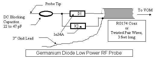
| RF Probe | Make your own for your VOM if a ‘scope is not handy! |
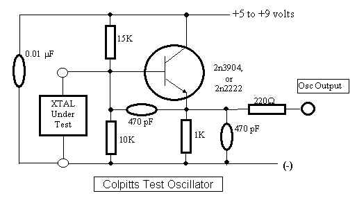
| Test Oscillator | Quartz crystal qualification, receiver testing. |
| Multi-band Receiver | With "S" Meter for VFO tests, Oscillator checks. Digital tuning a plus!! |
| FET Multi Meter | i.e. Radio Shack #22-216 FET Analog V.O.M. |
| Frequency Counter | Opto Electronics 3000A |
| 10.106 mHz Crystal | Receiver checking and QRP call frequency spotting if a frequency counter is not available. (do not connect oscillator directly to the receiver input) |
Use this probe for DC voltages under 25 volts; RF voltages under 25 volts P-P.
Use with a VOM with a high impedance FET input. Connect the ground lead as close as possible to the ground of the circuit under test.
Parts List for the NN1G CW XCVR
30 Meter Version Components
Resistors |
Capacitors |
Semiconductors |
|||||||
Qty |
Qty |
Qty |
|||||||
2 |
470W | 6 |
150 pF | Silver Mica … | 3 |
NE612 | Osc, Mixer | ||
4 |
10K | 3 |
330 pF | Silver Mica … | 1 |
MV1662 | Varactor | ||
2 |
10W | 4 |
47 pF | Silver Mica … | 8 |
1n4148 | Diodes | ||
2 |
470K | 1 |
5 pF | Silver Mica … | 3 |
2n2222A | npn transistors | ||
4 |
1 MW | 2 |
220 pF | Silver Mica … | 1 |
2n3906 | pnp transistor | ||
1 |
47K | 1 |
680 pF | Silver Mica … | 1 |
MPF102 | N chnl JFET | ||
1 |
4.7MW | 2 |
10 pf | Ceramic COG | 1 |
1n4737AT | 7.5volt Zener | ||
3 |
22K | 1 |
22 pF | Ceramic COG | 1 |
1n5256 | 27 volt Zener | ||
5 |
1 K„ | 1 |
68 pF | Ceramic COG | 1 |
78L09ACZ | 9V. Regulator | ||
1 |
2.2K | 3 |
270 pF | Ceramic COG | 1 |
RCA-4013 | 2n3553 equiv | ||
3 |
100W | 0 |
1 |
TLO-72 | Dual OP Amp | ||||
1 |
1000pF | Polyester | 1 |
1n5234 | 6.2 volt Zener | ||||
Trim Pot |
2 |
0.0022„ | Polyester | ||||||
1 |
200W | 1 |
0.0047 | Polyester | |||||
1 |
0.033 | Polyester | |||||||
| Potentiometers | 13 |
0.01uF | Polyester‚ | ||||||
1 |
100K ƒ | 3 |
0.1 uF | Polyester | |||||
1 |
5K | 1 |
820 pF | Polypropolene | |||||
2 |
47 uf | electrolytic | |||||||
1 |
65 pf | SG3009 trim cap | |||||||
3 |
65 pF | 6mm trim Cap | |||||||
1 |
3.3 m F | electrolytic | |||||||
1 |
100 uF | electrolytic | |||||||
1 |
47 uF | electrolytic | |||||||
RF Chokes |
Ferrite Materials |
Quartz Crystals |
|||||||||||
Qty |
Qty |
Qty |
|||||||||||
1 |
4.7 uH | 4 |
FT37-68 | Toriod Cores | 4 |
8.192 mHz | Crystals | ||||||
1 |
10 uH | 2 |
FT25-43 | Toriod Cores | |||||||||
1 |
FT37-61 | Toriod Cores | |||||||||||
= See Components substitution chart on the next page.
‚ = Quantity adjusted. Quantity understated in the original parts list.
ƒ = Ten turn potentiometer for the main tuning.
„ = Quantity adjustment due to the process of component substitution.
Component Substitutions
The impetus to become creative with this project was driven by several factors:
Seq # |
Original Component |
Substitute Component |
Remarks |
|
| 510KW , ¼ watt, 5% | 470KW ,¼ watt, 5% | Close enough. | ||
Y1-Y4 |
8.000 mHz quartz crystal | 8.192 mHz Quartx Crystal | They were FREE! | |
U1,3,5 |
NE602 osc, Mixer | NE612 osc, mixer | Easier to obtain. | |
Q5 |
2n3553 | RCA-4013 | Equivalent Device | |
L1 |
T50-2 Toriod, 27T, 3.6uH | FT37-68 Toriod, 25T, 5.5 uH | Lower VFO Frequency | |
L4 |
FT37-43 Toriod, 4T, 7 uH | FB-43-2401, 4 turns (8 uH). | 0.520 nH/T2 | |
L2, L3 |
T37-6 Toriod, 20 T | FT37-68 Toriod, 11T | 1.25 uH (8.8 nH/T2 ) | |
L5, L6 |
T37-6 Toriod, 15T | FT37-68 Toriod, 8T | 680 nH (8.8 nH/T2 ) | |
U4 |
NE5532 Dual Op-Amp | TLO-72 Dual Op Amp | Low noise, op-amp | |
U2 |
LM78L08, 8volt regulator | LM78L09, 9 volts | LM78L08 hard to find | |
D11 |
1n5257, 33 volts, ½ watt | 1n5256, 27 volts ½ watt | Close enough. | |
D10 |
1n5236, 7.5 volts, ½ watt | 1n4737AT 7.5 v.,1 watt | Close enough | |
T1 |
FT37-61, 11T, 4 T | FT37-68, 26T pri: 6T sec | 5.5 uH on pri.winding | |
T2 |
FT37-43, 4 bifilar turns | FB43-2401, 5 bifilar turns | 12 uH per winding | |
C8 |
27pf Trimmer, #SG3004 | 65 pF trimmer SG3009 | wider adjustment | |
C23, |
70 pF., 6mm trim cap | 65 pF., 6mm trimcap | Close enough | |
C26, |
70 pF., 6mm trim cap | 65 pF., 6mm trimcap | Close enough | |
C9 |
150 pF | 330 pF | Wider varactor range | |
C6 |
0.0047uf | 0.0022uF | Lower C/L ratio | |
C5 |
0.0047uf | 0.001uf (1000pF) | Lower C/L ratio | |
| 220 uF (next to D11) | 100 uF/ 16 volts | no 220 uf on hand! |
Approximate Parts Cost
Qty |
Description |
Cost ea |
Total |
||
1 |
Hosfelt #56-495 wall cube | 1.75 |
1.75 |
||
1 |
10 Turn Pot., 100KW | 9.95 |
9.95 |
Main Tuning | |
1 |
5 KW Potentiometer | 2.00 |
2.00 |
RF Gain Control | |
27 |
Carbon film 5% resistors | 0.02 |
0.54 |
||
17 |
Silver mica Capacitors | 0.25 |
4.25 |
||
8 |
Ceramic COG Capacitors | 0.10 |
0.80 |
Temperature stable | |
18 |
Polyester caps <0.01 uf | 0.10 |
1.80 |
Low loss, temperature stable | |
3 |
0.1 uF polyester 50 volt caps | 0.30 |
0.90 |
||
1 |
SG3009 65 pf Trimmer | 1.50 |
1.50 |
||
3 |
65 pF 6 mm Trim caps | 0.45 |
1.35 |
||
3 |
Electrolytic Caps | 0.25 |
0.75 |
||
2 |
FB43-2401 ferrite bead core | 0.30 |
0.60 |
||
5 |
FT37-68 ferrite cores | 0.60 |
3.00 |
||
2 |
Molded RF chokes, 4.7, 10uH | 1.25 |
2.50 |
||
4 |
8.192 mHz quartz crystals | 1.00 |
4.00 |
||
1 |
MV1662 varactor | 0.33 |
0.33 |
||
3 |
NE612 Osc., Mixer | 2.75 |
8.25 |
||
8 |
1n4148 Diodes | 0.10 |
0.80 |
||
3 |
2n2222A | 0.10 |
0.30 |
||
1 |
MPF102 | 0.30 |
0.30 |
||
1 |
2n3906 pnp transistor | 0.10 |
0.10 |
||
1 |
2n3553, RCA #4013 | 2.50 |
2.50 |
||
1 |
200 ohm trimpot | 1.00 |
1.00 |
||
1 |
1n5234 or 1n753 zener diode | 0.25 |
0.25 |
||
1 |
1n4737AT Zener diode, | 0.25 |
0.25 |
||
1 |
1n5256 Zener Diode, 27v. | 0.30 |
0.30 |
||
1 |
LM78L09ACZ | 0.80 |
0.80 |
||
1 |
TLO-72 or TL0-82 op-amp | 0.80 |
0.80 |
||
1 |
Printed Circuit Board | 6.00 |
6.00 |
||
NOTES and HINTS
FERRITE CORES. Most of the ferrite cores used for tuned circuits and filters in this version project are #FT37-68. #68 ferrite material has excellent temperature stability, and excellent high frequency characteristics.. The relative permeability of #68 material is 20. This means that #68 ferrite will yield the same inductance with fewer turns with larger guage wire (and hence decreased distributed capacitance and copper losses) as an iron powered core.
The higher permeability of #68 ferrite also introduces a tradeoff: a drastic reduction in resolution for low inductance values. Another caution is that higher permeability cores can saturate at lower ampere turn levels that less dense ferrites of the same size. Tell tale signs of this condition are heating of the cores and overheating of the Final RF Amplifier. However, this is not a problem with QRP power levels in this design.
A fractional turn in a toroidal inductor does not exist. Each pass through the core is a full turn. Inductance can change very rapidly since inductance is related to turns -squared (N2). When it appears that only a few turns get you to a target inductance, it is time to consider a less dense core with a lower permeability.
NE612 OSC-MIXER. NE602’s out of stock at Dan’s Small Parts and Kits at the time of our order; but, he sez that "‘612’s will work fine". Sure enough, he is right!!
QUARTZ CRYSTALS. The 30 meter version recommends 8.000 mHz quartz crystals. However, we happened to have a nice stock pile of 8.192 mHz crystals. We must have been lucky. Out of the first 10 crystals tested in a Colpitts oscillator, eight(8) of them were within a 100 hz band of each other. The crystals were numbered, and their oscillation frequency was recorded. The "SORT" feature of MicroSoft WORD-6 ranked the crystals by frequency.
SIDETONE...The xcvr has sidetone! The peak frequency response of the audio chain is approximately 800 Hz. You can experiment with C16 to make Y3 oscillate 800 Hz higher than Y4. Hmmmm! Do you suppose that there is potential here for a varactor tuned sidetone?? This would not be the same thing as R.I.T.
The amplitude of the sidetone can be increased by decreasing the 4.7MW resistor next to FET transistor Q1
KLUTZ DIODE. Nothing is more frustrating than applying reverse DC power accidently to a project and letting the smoke out of the parts. A silicon rectifier (i.e. 1n4004 rectifier) was installed with the Cathode soldered at the V+ tie pad of the PC board. A wire from the plus (+) side of your power supply would of course be connected to the anode of the klutz diode.
WALL WARTS. The output voltage of a 12 volt wall type AC to DC power adapter may go as high as 16 volts under light loading conditions. Since most of the XCVR board is protected by a voltage regulator, the higher than normal voltage should not be a problem. DC wall type supply cubes are not well regulated. However, their power limitations can avert a disaster should an accidental short occur in the test phase of your project. HOSFELT ELECTRONICS has a series of DC power adapters for sale. It is recommended that an adapter with a current output rating of no more that 500 mA be used. The #56-495 or #56-496 "wall warts " from HOSFELT are rated for 12 volts @ 300mA; price is $1.75. These particular units do not have a connector at the end of the DC cord.
78L08 VOLTAGE REGULATORS. These seem to be very hard to find. Another parts list adjustment was made by choosing the 78L09. However, there is a gotcha here. The output of this voltage regulator also determines the bias level for the Dual Op-Amp and tuning range of the Varactor. By making a strategic cut on the solder side of the board, a 6.2 volt zener (1n5234 or 1n753) was placed as to provide a bias supply voltage of 6.2 volts. This nicely biases the Op-Amp outputs to be midway between the Gnd and +V supply rails. The new Vr allows the tuning range to be spread out on 9 turns of the tuning pot instead of 5 turns.
Be very careful here!
A PC trace cut is required to break the connection between the Vr pad and pin 1 of Voltage Regulator U2. The trace cut can be made on the solder side of the board under neath capacitor C18 or jumper wire W1. Refer to your assembly drawing that came with the PC board.
If your "B+" supply is consistantly in the 13-15 volt range, don’t worry about doing this modification.
Schematic equivalent of partitioned regulated voltage for Op-Amp Biasing and Varactor Ranging.
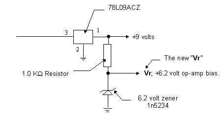
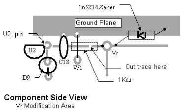
*Connect the1K resistor across the PC trace cut.. The anode of the zener gets connected to the ground plane: the cathode next to the Vr pad. Parts can be mounted on the solder side.
Assembly Sequence
Assemble the PC board by installing the passive components first: the active components last.
Passive Components
Installation of all passive components will allow you the clean up the work area, and also keep better track of the few remaining active parts to be installed later.
Active Components
VFO
Receiver Section
Transmitter
Save Q6 as the very last part to be installed on the board. The driver transistor Q5 is already terminated with 100W . Once you have the rest of the rig working and have verified that there is drive from Q5, it is safe to install Q6 for dummy load testing.
VFO Alignment
The best place to start with this project is with the VFO, since it is common to transmitter and receiver operation.
The VFO was tested with the original component values given by NN1G. The approximate frequency recorded on a frequency counter at pin 2 of U5 was in the neighborhood of 2.1 mHz.
The receiver mixer injection point (U5 pin 2 ) was used for tuning range measurements because the test probe of the frequency counter approximates the loading factor presented by U5.
The original tuning range of the VFO as designed by NN1G was very interesting.
The tuning range was barely 20 kHz. Perhaps NN1G had intended operation within a small band segment that included the QRP calling frequency. The QST article mentions that one of the operating techniques is to stay away from "Kiliwatt Alley". However, on 30 meters, the maximum power is 250 watts.
Also, the frequency of the VFO was too high for the 8.192 mHz IF chosen for this project. NN1G had designed the project for an IF frequency of 8.000 mHz. Thus, the VFO had to be shifted down about 200 kHz to make "the numbers" come out correctly.
Redesigning the VFO
VFO Frequency Range.
To make the project operate within the 30 meter band, the VFO tuning range had to include frequencies from 1.908 kHz through 1.958 mHz.
Low End |
High End |
|
| VFO Frequency | 1.908 |
1.958 |
| IF Frequency. | 8.192 |
8.192 |
| Carrier Frequency | 00 |
0 |
The alignment of the VFO can be checked on a receiver that is capable of covering the 160 meter amateur band.
The VFO is quite stable. The high "C" to "L" ratio, and its relatively low frequency of operation contribute to its stability. The relative large values of net capacitance of the VFO tank circuit make it less sensitive to proximity effects. Of course, when the completed project is housed in a metal enclosure, stray capacitance is a moot point.
Dope your coils with polyurethane (fingernail polish) and glue ‘em down to prevent vibration induced frequency modulation!
Changes to the VFO Parts List
The follwing table is a list of athe component changes that were made to adapt the VFO to the new IF frequency of 8.192 mHz.
Seq # |
Original Component |
Substitute Component |
Remarks |
| L1 | T50-2 Toriod, 27T, 3.6uH | FT37-68 Toriod, 25T | 5.6uH (8.8 nH/T2 ) |
| C8 | 27pf Trimmer, #SG3004 | 65 pF trimmer SG3009 | wider offset tuning range |
| C9 | 150 pF | 330 pF | Wider varactor range |
| C6 | 0.0047uf | 0.0022uF | |
| C5 | 0.0047uf | 0.001uf (1000pF) |
Tuning Range Factors.
One of the limiting factors was the D C tuning range of the varactor diode when compared to the baseline capacitance contributed by C5 and C8. The series equivalent capacitance of C5 and C8 had to be lowered in order to make the varactor more effective.
Tuning range is also dependent on the RF sinewave applied to the varactor.
Maximum tuning range is obtained when the bias voltage adjustment range is large when compared to the peak-to-peak amlitude of the RF sinewave that is applied to the varactor.
This is one of the critical factors in varactor tuned oscillator design. In circuits where the tank circuit handles a large RF sinewave, the sinewave modulates the varactor, and thus limits the effects of the tuning control voltage.
VFO Alignment Hints
. Proper operation can be checked with another receiver, or a frequency counter.
Typical MV1662 Varactor Diode Characteristics.
The test conditions for the following measurements:
VT |
Capacitance |
1 |
450 pF |
2 |
320 pF |
3 |
220 pF |
4 |
143 pF |
5 |
90 pF |
6 |
60 pF |
7 |
44 pF |
8 |
37 pF |
VFO Range after Modification
C8 @ 50% mesh |
||
Low End |
High End |
|
| VT, Tuning Voltage | 0 Volts |
9 Volts |
VFO Frequency |
1.902 |
1.977 |
IF Frequency. |
8.192 |
8.192 |
Carrier Frequency |
The wider adjustment range of C8 results in a shift range of +/- 15 kHz.
Construction Notes
Printed Circuit Board
The Board does not have a silk screen overlay that marks location and orientation of the components. You will have to refer to the components placement drawing and the schematic to sort things out.
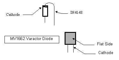
Diodes
Diodes are mounted as a radial lead components, with the cathode facing away from the board. All of the diodes, with the exception of the 1n5256 Zener, are mounted into the PC board by using the hairpin bend on the cathode lead.
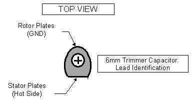
6mm Trimmer Capacitors
The trimmer capacitors, C23 and C26, should be mounted with attention given to grounding the rotor plates. The outer shell and the rotor plates form a shield that prevents detuning due to proximity effects.
NE602-NE612 Operating Voltages
DC operating voltages on all pins of the NE602-NE612 Osc-Mixer chips were measured with a Radio Shack #22-216 analog FET VOM.
Measurements were made at U1 and U3 after the receiver was aligned and working.
Pin # |
DC voltage |
Pin Function |
1 |
1.4 |
RF input pin |
2 |
1.4 |
RF input pin |
3 |
GND |
|
4 |
7.2 |
IF Output |
5 |
7.2 |
IF Output |
6 |
8.3 |
Osc Input. Also VFO injection point @ U1 |
7 |
7.6 |
Osc output |
8 |
8.4 |
V+ via diode D9 |
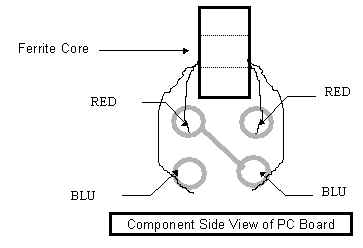
Transformers
Transformer T2.
This transformer was made by winding 5 turns onto a #43 ferrite FB43-2401 Ferrite Bead Core. Wires with insulation of two different colors were used to make identification of the windings possible.
The windings are connected in series to form a 2:1 step-down auto transformer.
The site location on the PC board can be a little confusing.
Our suppliers:
![]()
![]()
![]()
![]()