 G4GXO Dual-PIC DDS VFO
|
|
|
Original
Schematic
Original
WB2V DDS VFO Article |
Making
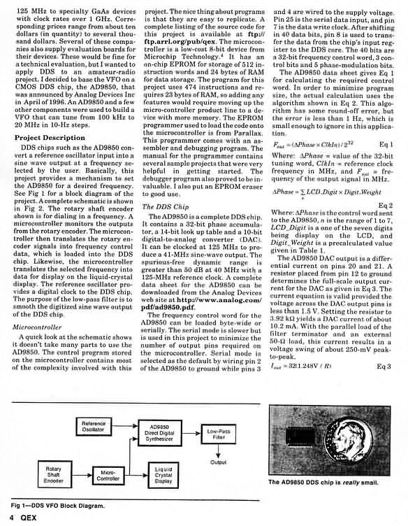
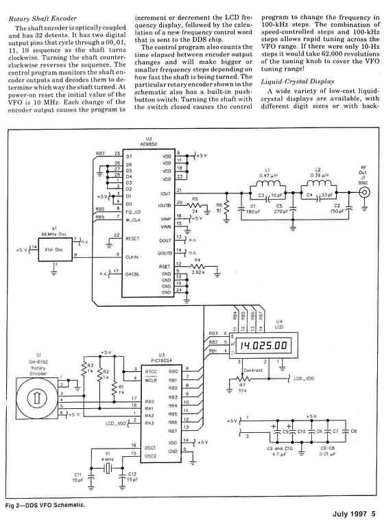
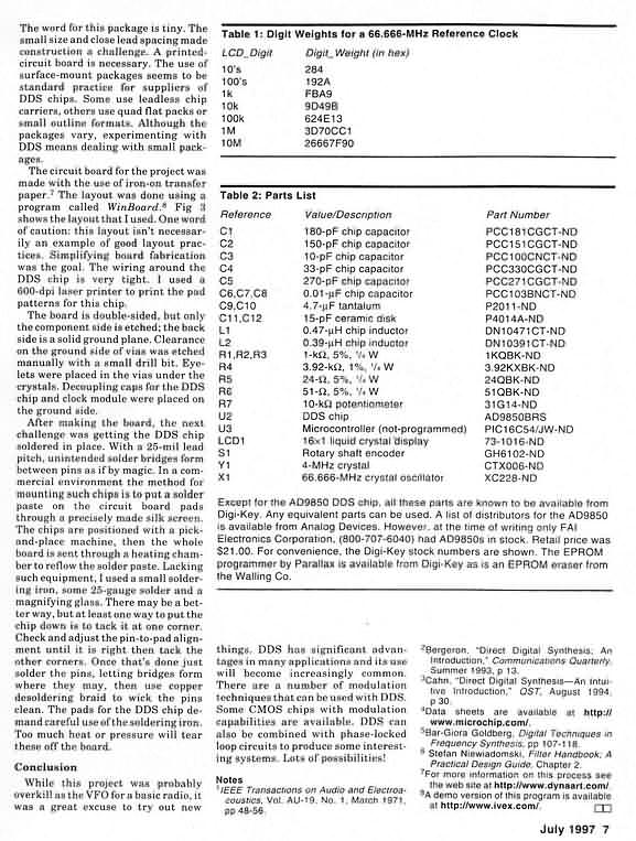
a Dual-PIC Version Some years ago, specifically in July of 1997, Curtis Preuss, WB2V presented a mini-landmark article in the pages of QEX entitle "Building a Direct Digital Synthesis VFO". Curt had obtained one of the then-new AD9850 DDS chips from Analog Devices and he constructed an experimenters breadboard consisting of that DDS chip, a PIC microcontroller and an LCD display in order to demonstrate the ease and flexibility of producing a fair quality, digitally constructed VFO. FAR Circuits provided the pc board then (still available today), and many homebrewers used this DDS project over the years as the basis for their own DDS VFO experimentation. In fact, in that same era, the Ham-PIC users group formed and a number of us started optimizing the original PIC16C54 program, adding extra capabilities, converting over to the more user-friendly PIC16F84, and generally learning lots about PICs and DDS chips along the way. An entire collection of these mods and software updates is posted on the Ham-PIC Resource website. (See Note 4 for the web pages address.) The Original Circuit The entire DDS VFO article is posted, with permission from the ARRL and from WB2V, in the 6 links to the left on this page. The schematic itself is reproduced in Figure 1 for easy reference. A Microchip PIC16C54 is the heart of the project, taking input from a shaft encoder S1 and sending frequency control commands to the AD9850 DDS at U2. The LCD (U4) displays the specific frequency being output by the DDS. The DDS chip contains a 32-bit phase accumulator, a 1-bit look up table and a 10-bit D-to-A converter. When clocked at 66 mHz, a maximum usable frequency of 20 mHz is possible after applying a low pass filter as shown on the "Iout" output pin 21. The DDS frequency is set by the PIC sending a 32-bit frequency control word, 3 control bits and 5 phase-modulation bits serially to the 9850. Turning the shaft encoder commands the PIC microcontroller to send new frequency and phase information to the DDS, which is also reflected in a new text string sent to the LCD. The Evolution Begins Several homebrewers were quite active on the Ham-PIC mail list, contributing their observations and modified programs to the Resource Page for others to use. Craig Johnson (AA0ZZ), Bruce Stogh (AA0ED), and most recently Chuck Olson (WB9KZY) have made some of the more prolific changes to WB2Vs the original design, adding calibration, memories, altered tuning rates, and more. Another notable homebrewer experimenting with the code was Ron Taylor, G4GXO. Ron decided that the tuning was too slow when used as a VFO in his custom-designed transceiver and he determined that he could significantly speed up the tuning rate by splitting the control and display software in the PIC into two PICs which is where our real story actually begins this time, told in Rons own words. Fast Tuning DDS System Using 2 PICs "After building and using an AD9850 DDS synthesizer based upon information from several DDS and PIC projects, I very quickly came to appreciate one of the chief limitations of the single-PIC control system, particularly when used in synthesizers employing a "slow" LCD frequency display. "The problem with the type of configuration shown in Figure 1 is that for every tuning step the processor has to perform a complete program cycle, often involving long iterative computations and slow dialogue with the LCD processor. The time taken for these activities limits the number of frequency tuning steps that the system can execute over a given time period, and if not compensated for in some way, it would produce and unbearably slow tuning rate. A couple of techniques are usedto overcome this. Firstly, variable rate tuning is used whereby the frequency step size increases with the speed of rotation of the tuning control. Secondly, a rotary encoder of relatively few increments per revolution is used to allow a reasonable rotation rate with the variable step rate function. "I found the variable rate tuning off-putting and at times difficult to use. After attempting without success to improve on the scheme, I decided to try a new approach, with the aim of producing a true "VFO feel" to the tuning. "I rebuilt the synthesizer, exchanging my home made 32-step ex-PC mouse shaft encoder for a reasonably priced 512-step HEDS 9100 encoder from Farnell. I then adapted a fine piece of software called siggen3a, jointly developed by WB2V, AA0ED and AA0ZZ. This software was designed to operate on a single PIC DDS system for use as a signal generator or local oscillator for direct conversion transceivers. The very logical program structure and highly comprehensive line documentation was a real benefit. Having never programmed PICs before, I used this program as a combined tutorial and crash course in 16F84 programming! I first modified the LCD routines slightly to make them compatible with my display. Next, I added an IF offset routine to adapt the system for use with my Belthorn SSB IF module. Once I checked that the software worked in a single PIC system, I took the bold step of splitting the software into two programs each running on a 16F84 PIC one to scan the controls and manage the DDS, and the other to convert binary frequency data into ASCII and manage the LCD. A simple serial interface allows the two PICs to communicate. "Referring to Figure 2, both PICs are clocked at 8.86 mHz (my transceiver has a 10 mHz IF and these crystals just happened to be available and were far enough away from the IF frequency so as to avoid interference.) "The key to increasing the system tuning speed is that both processors run independently, allowing the tuning and display processes to run in parallel until the LCD PIC calls for the current frequency. When this happens, the DDS PIC passes the frequency word over the serial interface and resumes scanning the controls and managing the DDS. Once it has received a new frequency update, the LCD PIC processes it, formats it and feeds it to the LCD processor for display. An additional 10ms delay in the frequency request routine further increases the time available to the DDS PIC for the tuning process. The result is a nice "VFO-like" tuning action with 10 Hz steps and a 10 kHz per revolution (double encoder size) tuning rate. Despite the resultant display lag and delays, the processes run fast enough so as not to be noticeable to the eye. The tuning action limits at about 2 revolutions per second. With further program and hardware optimization, this could be increased significantly. For example, the IF shift routine resides in the DDS PIC to allow USB/LSB switching with my single crystal carrier oscillator and typically asymmetrical ladder filter. With two carrier crystals and a symmetrical lattice filter, this routine could reside in the LCD PIC, freeing up processor time for the tuning routines." Reproducing the Dual PIC DDS VFO Recalling that in this portion of our Digital QRP Homebrewing column we like to present modifications to already-available kits, well next present some guidelines for those readers wishing to create a dual-PIC version of the original WB2V DDS VFO. The first order of business is getting the original VFO circuit built and working. The circuit boards are still available from FAR Circuits (see Notes section), as are the AD9850 DDS chips. The more modern PIC16F84 can be used in place of the 16C54 and the software is available on the Ham-PIC Resource Page. Once the original DDS VFO is working (or perhaps you had one built previously!), you can add the second PIC, following the schematic in Figure 2. The software for each PIC processor in the G4GXO system is downloadable from our columns companion website just program the PICs using your EPIC programmer, MPLAB, or whatever convenient method you have to get the programs into the PICs. Since the time of G4GXOs experimentation, Craig, AA0ZZ and Bruce AA0ED have evolved and optimized this dual-PIC solution even further. You can see their software programs on the Ham-PIC Resource Page. So There You Have It Theres no reason why you too cannot have a DDS VFO and play alongside the digital guys. My DDS VFO is used at times as a plug-in replacement for the VFO in my Sierra transceiver, as a signal source for the bench, or as an LO for a direct conversion transceiver the possibilities are endless!
Page last modified:
May 20, 2002
|