Atlanticon Kit: The Crystalizer
10 MHz VXO ... with a twist!
![]()
Atlanticon Kit: The
Crystalizer
10 MHz
VXO ... with a twist!
![]()
This years Atlanticon Kit was a 10 MHz variable crystal oscillator, or VXO, that can be put to use in many ways around the shack. Once calibrated to WWV, this VXO can serve as an accurate frequency standard for receiver alignment, or as a PLL standard, or even as an LO for a transmitter.
The twist with our Atlanticon Kit this time was not in the construction of the circuit, as we are provided a pc board, but in the accuracy and stability of the oscillator itself. Weve provided the basic oscillator and buffer circuits, but it was up to the builder to provide any means possible to bend the crystal in order to place the oscillator dead-on 10 MHz and keep it there in the presence of changing ambient temperatures. Especially during the annual construction contest held on Saturday evening at Atlanticon!
Capacitors, crystals and semiconductors have temperature coefficients that represent how the component values change with changing temperature. When the component values change, the oscillator frequency changes. This drift is not good if you want a very stable and unchanging oscillator frequency.
So the real fun challenge for the builder is to find ways to dynamically adjust, compensate or insulate the circuit against temperature changes. The Adjust signal on connector P1 pin 1 can be a simple potentiometer that presents a nominal 4 volts to varicap D1, but thats only a static level and if the temperature changes, the pot setting would need to be changed to compensate for that change . One could instead dynamically adjust that control signal in accordance to the ambient temperature. Or perhaps judicious placement of negative coefficient capacitors in the circuit could compensate for drift. An insulated enclosure, or a temperature-controlled oven would also be possible solutions!
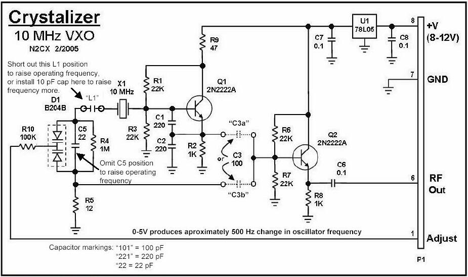
CRYSTALIZER SCHEMATIC -- Note that we found it better to omit L1 and C5 in order to allow the frequency-adjustability range to definitely reach 10 MHz. Otherwise, with these parts in place, some units cannot quite reach 10.000 MHz when using the Adjust control input line. Thus L1 and C5 were not included in the second round of 200 Crystalizer kit shipments. The C5 spot on the board should just be left open, and the L1 pads should be shorted together.
So you see, there are many opportunities for the builder to exhibit ingenuity and creativity in making this circuit stable and this was the basis for the contest held on Saturday evening at Atlanticon 2005. The circuits were judged on how accurate it was (think WWV beat frequency) and how stable it was in the face of changing ambient temperature (think heat gun).
The Crystalizer produces an approximate 2V p-p signal at RF Out when C3 is in the top position (C3b on the pcb). This signal is quite ragged but very suitable for driving a balanced mixer like an SA612. (Think producing a beat frequency with the WWV RF signal being placed on the other input of the mixer.) When C3 is placed in the lower, C3a position on the pcb, a 200 mV p-p near-pure sinusoid is delivered at RF Out, suitable for transmission, after amplification, if desired.
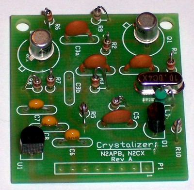
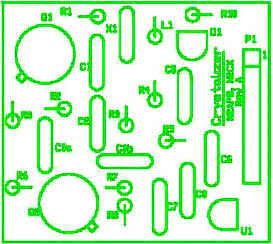
Construction of the Crystalizer is straightforward just use the schematic as a guide for placement of the components at the silkscreened locations on the board. Resistors are mounted on end with the top lead bent over and going into the hole next to the bottom lead.
Have fun with the Crystalizer and be creative with control of its temperature stability ... how close do you think you can get your Crystalizer to WWV? ;-)
Availability
Sorry, this kit has been retired and is no longer
available.
![]()
![]()