![]()
![]()
Application Note #8
![]()
Subject: Rainbow Configuration &Power Handling
"What part of the rainbow tuner makes it SWR absorbing? How does it work? And how much power can the SWR meter portion of the rainbow tuner handle before it gets fried? I would like to build the display in an existing tuner that I have, but I would like it to be able to handle 25 to 50 watts. What component would I need to change to increase the wattage?"
Joe N2CX responds ...
The part of the Rainbow that absorbs the RF power is the SWR bridge itself. If you redraw the circuit you can see that it actually has the form of a Wheatstone bridge:

Of course this does not show the diode detectors that sense the forward and reverse samples. At any rate, the resistors form voltage dividers that attenuate the input RF. If the antenna (at ANT/OUT) is exactly 50 ohms, the voltage across it will be exactly half the IN signal from the transmitter. And, since P = E*E/R, the output power is 1/4 the input power or 6 dB lower.
There are several things you can do to increse the power rating of the bridge. In fact they are the subject of an upcoming article for one of the QRP journals! I will briefly list them:
1. You could increase the power rating of R1, R2 and R3. Of course this would be tough to do on the existing pc board.
2. You could use the SWR sensing circuitry with an external SWR bridge like the one that Doug DeMaw and others employ. To do this, you could feed the rectified forward and reverse samples to the cathode of D1 and D2, respectively.
3. To use the existing bridge, all you have to do is to reduce the input power to the bridge with an attenuator so that it does not see more than 5 watts. Since you have to switch the Rainbow bridge out of line after adjustment anyway with this method, you simply put the attenuator in series with the Rainbow bridge and switch both in or out of line as in the following figure:
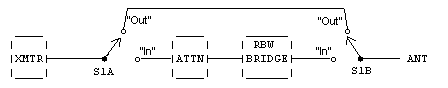
S1A and S1B are ganged so that in the "out" position they bypass the attenuator and Rainbow bridge, and while in the "in" position the transmitter output goes to the attenuator and the Rainbow bridge output goes to the antenna.
The attenuator can take any of several forms. The simplest is the common Tee or Pi pad as shown in the ARRL Radio Amateur's Handbook and other references. There are other forms of attenuators that are not necessarily exactly impedance-matched to 50 ohms, but are simpler to build. One thing you have to keep in mind when you build the attenuators is that they should be designed to dissipate the full power output of the transmitter.
P.S. Please note that I did not say anything about the power handling capacity of the tuner portion of the Rainbow. That's another matter entirely!
72/73,
Joe E., N2CX
from Southern New Jersey, y'all
home: n2cx@voicenet.com
![]()
![]()
![]()
![]()