![]()
![]()
Application Note #12
![]()
Subject: More on Switching the Rainbow Bridge In/Out
I think that perhaps some explanation of the wiring in Figure 3 of the manual might be of some help to people.
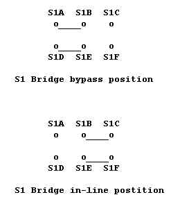
The bridge indeed should be bypassed during normal operation. This is done by switch S1 whose contacts are shown in the figure below. In the bridge bypass postition, switch contacts S1A and S1B are connected together by the upper switch arm, and S1D and S1E are connected together by the lower switch arm. RF comes in through the "hot" side of the XMTR IN coaxial connector through S1D to S1E and goes to S1A through the wire connecting the two switch contacts. It then goes through the upper switch arm to S1B and out to the "hot" side of the ANT coax connector. In this condition, there is no RF connected to the IN and OUT pins of the bridge since the switch arm is connected to the left-hand S1 contacts.
By the way, lest there be any confusion, the shield side of both coax connectors are permanently wired connected together with the GND pin on the pc board. The wires from the board IN pin goes to "only" S1F and the OUT pin goes "only" to S1C. There is no connection where the wires shown in the schematic diagram cross since there is no connection "dot".
With S1 in the other position, the Bridge is in-line with the tuner. Here S1E and S1F are connected together by the lower switch arm, connecting the XMTR IN RF signal to the bridge IN pin. Similarly S1B and S1C are connected together by the upper switch arm, so that RF from the bridge OUT pin flows to the ANT coax connector.
If the switch wiring is not as indicated, you will not be able to get correct SWR indications so be sure it wired up as per the above.
On the other hand you really don't even need the switch for bridge and tuner checkout. You can jsut wire the transmitter to the IN and GND pins and the tuner to the OUT and GND pins.
As noted on the errata sheet that came with your Rainbow, the board markings at the top right of the board (and Figure 3) are reversed. The top right-hand pin is really GND and the one directly underneath it is 50 OHMS. These must also be correctly wired for the Rainbow to work correctly.
Hope this all helps!
72/73,
Joe E., N2CX
from Southern New Jersey, y'all
home: n2cx@voicenet.com
![]()
![]()
![]()
![]()